-87-
Introduction
.BTUFS
TUBUJPO
4MBWF
TUBUJPO
4MBWF
TUBUJPO
4MBWF
TUBUJPO
4MBWF
TUBUJPO
4MBWF
TUBUJPO
4MBWF
TUBUJPO
1SPIJCJUFE
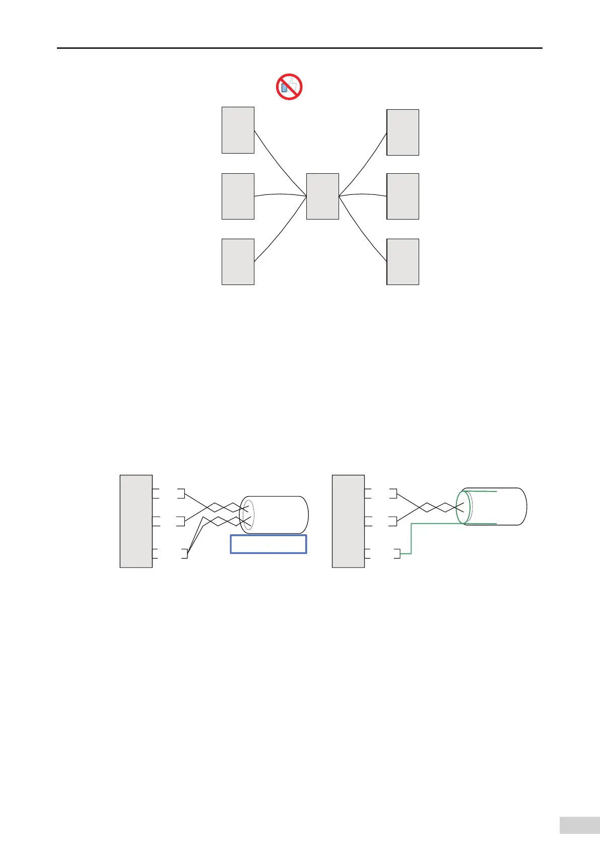
Figure 5-31 Incorrect star-shaped connection mode
■
Terminal wiring mode
① For nodes with the CGND terminal
Check whether the RS485 bus contains three cables that connect to the 485+
,
485-
,
and CGND terminals
and ensure that the terminals are not connected incorrectly or reversely. If shielded cables are used
,
the
shield layer must be connected to the CGND terminal. At any node or middle position
,
the shield layer
cannot connect to any position (including the machine housing and device ground terminal) other than
the CGND terminal of the node.
Due to attenuation in the cable
,
you are advised to use AGW26 or thicker cables if the cable length
exceeds 3 m and use twisted pair cables to connect the 485+ and 485- terminals at any time.
OPEF
$(/%
$(/%
.VMUJDPSFVOTIJFMEFE
4IJFMEFEUXJTUFEQBJS
OPEF
a multi-core unshielded cable b shielded twisted pair
Figure 5-32 Terminal wiring
Recommended cable 1: multi-core cable with twisted pairs. Use one of the twisted pairs as the
connection cable for the 485+ and 485- terminals
,
and twist others into one as the connection cable of
the CGND terminal.
Recommended cable 2: twisted pair cable with a shield layer. Use the twisted pair as the connection
cable for the 485+ and 485- terminals
,
and use the shield layer as the connection cable of the CGND
terminal.
If the shield cable is used as the connection cable
,
ensure that the shield layer is only connected to the
CGND terminal but is not connected to the main earth of the site.
② For nodes without the CGND terminal
If the node does not have the CGND terminal
,
do not connect the CGND or shield layer to the PE of the
node
,
but use the following methods:
 Loading...


