2 Wiring
2
- 13 -
especially when the power supply is for powering up multiple drives or brakes. Insufcient power supply will
lead to lack of supply current, thus causing failure of the drives or brakes. The brake shall be powered up
by a 24 VDC power supply. The power must match the motor model and meets the brake requirements.
1. Remove the jumper between terminals
and D of the servo drive when connecting a
regenerative resistor.
2. CN3 and CN4 are identical communication ports with the same pin denition, and either can
be used.
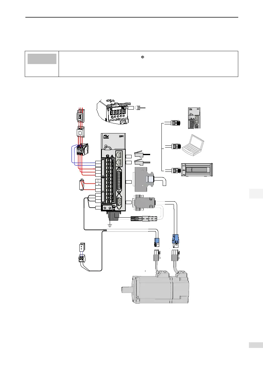
Figure 2-2 Wiring example of three-phase 220 V/380 V system
Servo motor main circuit cable
Servo motor
encoder cable
Servo drive I/O cable
(prepared by user)
Communication
cable for multi-drive
parallel connection
Note 1
Servo drive RS232
communication cable
P
CHARGE
L1C
R
S
-
D
C
U
V
W
CN1
CN2
CN4
CN3
CN5
PE
L2C
T
24 VDC
System
ground
Battery box
Servo drive to PC communication cable
Servo drive to PLC communication cable
Communication cable for multi-
drive parallel connection
Power supply
Three-phase
220/
380 VAC
Circuit breaker for
wiring
Noise filter
Electromagnetic
contactor
Turn ON/OFF power of the
servo drive. Install a surge
suppressor when using this
contactor.
Electromagnetic relay
Control signal to turn ON/OFF of the
brake power supply. Install a surge
suppressor when using this contactor.
Brake power supply
24
VDC power supply, used
when the servo motor is
configured with brake.
Regenerative resistor
I
2
P
-
S
5
5
R
6
0
S
The servo drive is directly connected to an industrial power supply, with no isolation such as transformer. In
this case, a fuse or circuit breaker must be connected on the input power supply to prevent cross electric
accidents in the servo system. The servo drive is not configured with the built-in protective grounding
circuit. Thus, connect a RCD against both overload and short-circuit or a specialized RCD combined with
protective grounding.
It is forbidden to run or stop the motor by using the electromagnetic contactor. As a high-inductance device,

 Loading...
