2 Wiring
2
- 12 -
Chapter 2 Wiring
2.1 Servo System Wiring
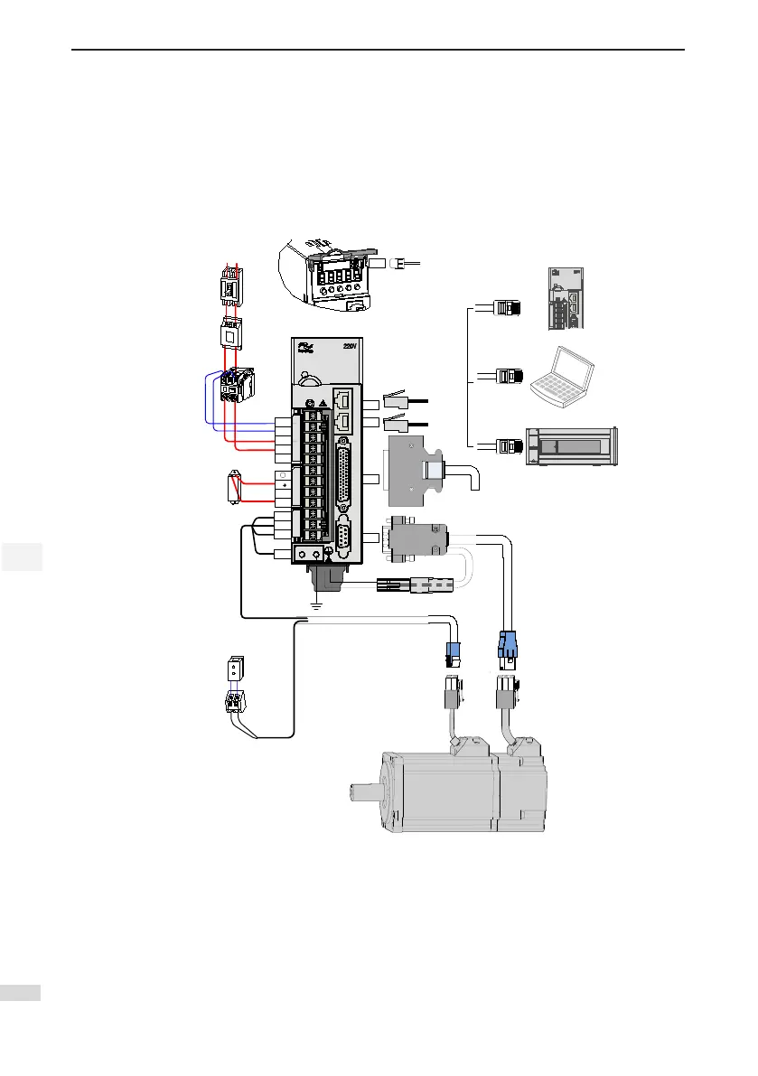
Figure 2-1 Wiring example of single-phase 220 V system
Servo motor main circuit cable
Servo motor
encoder cable
Servo drive I/O cable
(prepared by user)
Note 1
Servo drive RS232
communication cable
CHARGE
L1C
L1
L2
-
D
C
U
V
W
CN1
CN2
CN4
CN3
CN5
PE
L2C
24 VDC
System
ground
Battery box
Note
2
Servo drive to PC communication cable
Servo drive to PLC communication cable
Communication cable for multi-
drive parallel connection
Communication
cable for multi-drive
parallel connection
P
Power supply
Single-phase
220 VAC
Circuit breaker for wiring
Noise filter
Electromagnetic contactor
Turn ON/OFF power of the
servo drive. Install a surge
suppressor when using this
contactor.
Regenerative resistor
Electromagnetic relay
Control signal to turn ON/OFF of the
brake power supply. Install a surge
suppressor when using this contactor.
Brake power supply
24 VDC power supply, used
when the servo motor is
configured with brake.
I
2
P
-
S
5
5
R
6
0
S
The servo drive is directly connected to an industrial power supply, with no isolation such as transformer. In
this case, a fuse or circuit breaker must be connected on the input power supply to prevent cross electric
accidents in the servo system. The servo drive is not congured with the built-in protective grounding circuit.
Thus, connect a residual current device (RCD) against both overload and short-circuit or a specialized
RCCB combined with protective grounding.
It is forbidden to run or stop the motor by using the electromagnetic contactor. As a high-inductance device,
the motor generates instantaneous high voltage, which may damage the contactor.
Pay attention to the power capacity when connecting an external control power supply or 24 VDC,

 Loading...
