2 Wiring
2
- 24 -
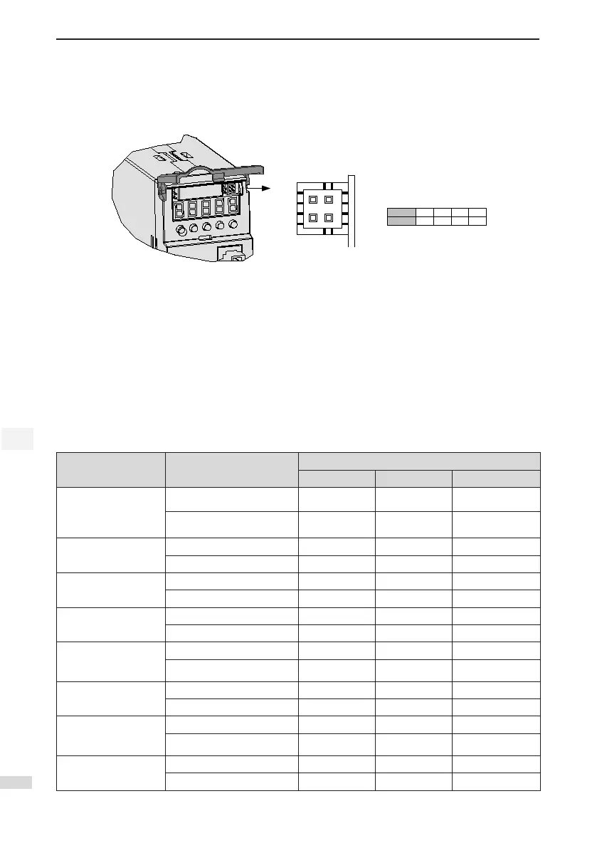
2.3.4 Analog Monitoring Signal Terminal Connector CN5
The following gure shows pin layout of the analog monitoring signal terminal connector CN5.
Figure 2-10 Analog monitoring signal terminal connector
1 3
2
4
No.
Definition
1
GND
2
AO1
3
GND
4
AO2
IS
620
P
-
S
5
R
5
Corresponding interface circuit:
Analog output: -10 to +10 V
Maximum output current: 1 mA
2.4 Cables
2.4.1 Cable Model
Servo Motor Power Cable and Encoder Cable
■
Models Without Brake
Motor Model Cable Type
Cable Length
L = 3.0 m L = 5.0 m L = 10.0 m
ISMH1-*******-U1***
ISMH1-*******-U2***
ISMH4-*******-U1***
ISMH4-*******-U2***
Power cable S6-L-M00-3.0 S6-L-M00-5.0 S6-L-M00-10.0
Incremental encoder cable S6-L-P00-3.0 S6-L-P00-5.0 S6-L-P00-10.0
ISMH1-*******-A3***
ISMH4-*******-A3***
Power cable S6-L-M00-3.0 S6-L-M00-5.0 S6-L-M00-10.0
Absolute encoder cable S6-L-P20-3.0 S6-L-P20-5.0 S6-L-P20-10.0
ISMH2-*******-U1***
ISMH2-*******-U2***
Power cable S6-L-M11-3.0 S6-L-M11-5.0 S6-L-M11-10.0
Incremental encoder cable S6-L-P01-3.0 S6-L-P01-5.0 S6-L-P01-10.0
ISMH2-*******-A3***
Power cable S6-L-M11-3.0 S6-L-M11-5.0 S6-L-M11-10.0
Absolute encoder cable S6-L-P21-3.0 S6-L-P21-5.0 S6-L-P21-10.0
ISMH3-*******-U1***
ISMH3-*******-U2***
(1.8 kW and below)
Power cable S6-L-M11-3.0 S6-L-M11-5.0 S6-L-M11-10.0
Incremental encoder cable S6-L-P01-3.0 S6-L-P01-5.0 S6-L-P01-10.0
ISMH3-*******-A3***
(1.8 kW and above)
Power cable S6-L-M11-3.0 S6-L-M11-5.0 S6-L-M11-10.0
Absolute encoder cable S6-L-P21-3.0 S6-L-P21-5.0 S6-L-P21-10.0
ISMH3-*******-U1***
ISMH3-*******-U2***
(2.9 kW)
Power cable S6-L-M12-3.0 S6-L-M12-5.0 S6-L-M12-10.0
Incremental encoder cable S6-L-P01-3.0 S6-L-P01-5.0 S6-L-P01-10.0
ISMH3-*******-A3***
(2.9 kW)
Power cable S6-L-M12-3.0 S6-L-M12-5.0 S6-L-M12-10.0
Absolute encoder cable S6-L-P21-3.0 S6-L-P21-5.0 S6-L-P21-10.0

 Loading...
