2 Wiring
2
- 23 -
Signal Default Function
Pin
No.
Function Description
General
DO4+ ALM+ 1
Fault output
DO4- ALM- 26
DO5+ HomeAttain+ 28
Homing completed
DO5- HomeAttain- 27
Encoder Frequency-Division Output Signal
Table 2-6 Encoder frequency-division output signal specications
Signal
Default
Function
Pin No. Function Description
General
PAO+
PAO-
21
22
Phase A output signal
Phases A+B quadrature pulse output signal
PBO+
PBO-
25
23
Phase B output signal
PZO+
PZO-
13
24
Phase Z output signal Home pulse output signal
PZ-OUT 44 Phase Z output signal Home pulse OC output signal
GND 29 Home pulse OC output signal ground
+5V 15
5 V internal power supply
Maximum output current: 200 mA
GND 16
PE Housing
The encoder frequency-division output circuit outputs OC signals via the differential drive. Generally, it
provides feedback signals to the host controller in the closed-loop position control system. A differential or
optocoupler circuit shall be used in the host controller to receive feedback signals. The maximum output
current is 20 mA.
2.3.3 Communication Signal Terminal Connectors CN3/CN4
The CN3/CN4 terminals of the servo drive are used for communication connection between the servo drive
and the PC, PLC, and other servo drives. The following table describes the pin denitions of the CN3/CN4
terminals.
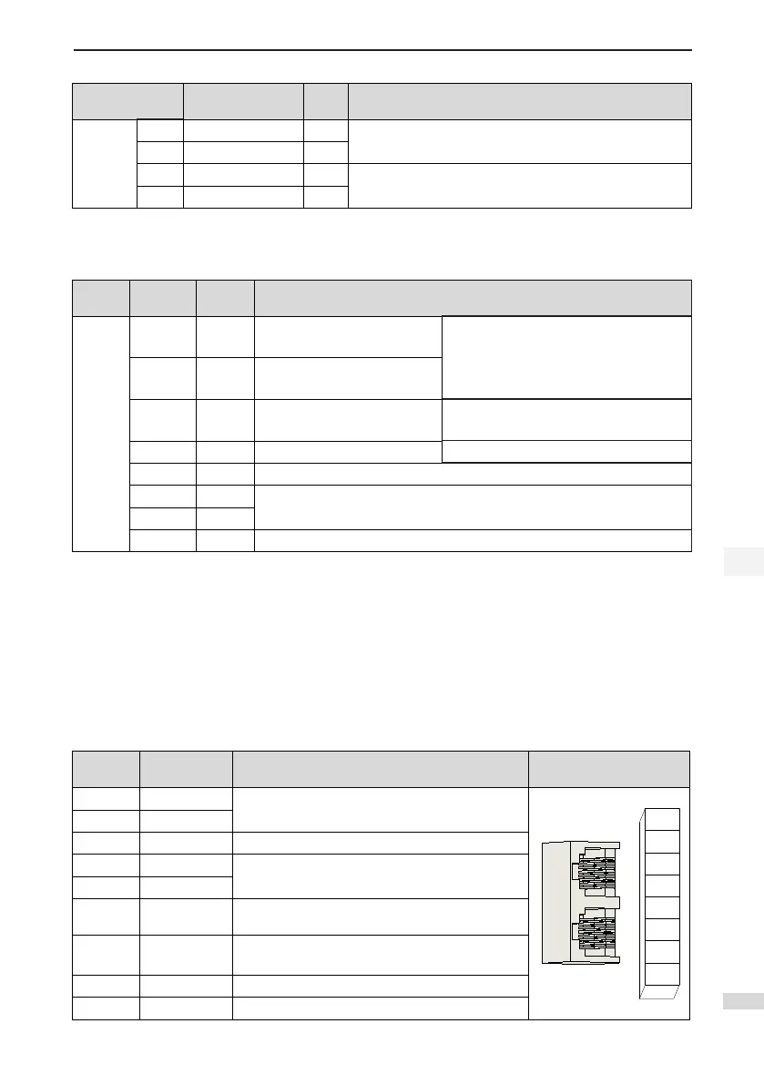
Table 2-7 Pin denition of communication signal terminal connectors
Pin No. Pin Description Pin Layout
1 CANH
CAN communication port
2 CANL
3 CGND CAN communication ground
4 RS485+
RS485 communication port
5 RS485-
6 RS232-TXD
RS232 transmitting end, connected to the receiving
end of the host controller
7 RS232-RXD
RS232 transmitting end, connected to the sending
end of the host controller
8 GND Ground
Housing PE Shield

 Loading...
