2 Wiring
2
- 22 -
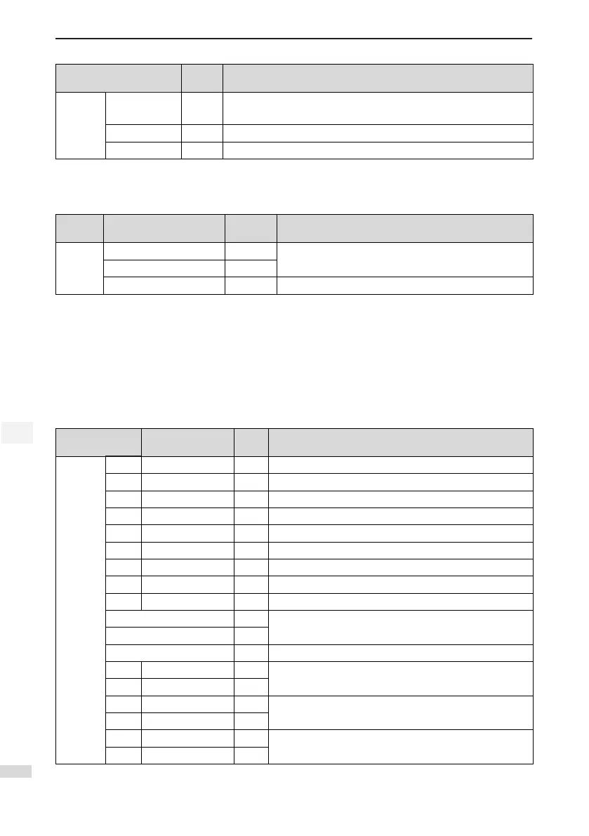
Signal Pin No. Function Description
Position
reference
HSIGN+
HSIGN-
42
40
High-speed position reference symbols
PULLHI 35 External power input terminal of reference pulse
GND 29 Signal ground
AI Signals
Table 2-4 AI signal description
Signal Default Function Pin No. Function Description
Analog
AI2 18
Ordinary analog input signals
Resolution: 12 bit; Input voltage: maximum ±12V
AI1 20
GND 19 Analog input signal ground
Speed and torque analog signal input terminals are AI1 and AI2, resolution of which is 12-bit. Corresponding
voltage values are set via group H03 parameters.
Input voltage range: -10 to +10 V; resolution: 12 bit;
Maximum permissible voltage: ±12 V;
Input impedance: ≈ 9 kΩ
DI/DO Signals
Table 2-5 DI/DO signal description
Signal Default Function
Pin
No.
Function Description
General
DI1 P-OT 9 Positive limit switch
DI2 N-OT 10 Negative limit switch
DI3 INHIBIT 34 Pulse input inhibited
DI4 ALM-RST 8 Alarm reset (edge valid)
DI5 S-ON 33 Servo ON
DI6 ZCLAMP 32 Zero speed clamp
DI7 GAIN-SEL 31 Gain switchover
DI8 HomeSwitch 30 Home switch
DI9 Reserved 12 -
+24V 17
Internal 24 V power supply, voltage range: 20 to 28 V,
maximum output current: 200 mA
COM- 14
COM+ 11 Power input (12 to 24 V)
DO1+ S-RDY+ 7
Servo ready
DO1- S-RDY- 6
DO2+ COIN+ 5
Position reached
DO2- COIN- 4
DO3+ ZERO+ 3
Zero speed
DO3- ZERO- 2

 Loading...
