EasyManuals Logo

Inovance MD210 Series User Manual

Inovance MD210 Series
48 pages
To Next Page IconTo Next Page
To Previous Page IconTo Previous Page
Page #9 background imageLoading...
Page #9 background image
Page 7 of 43
CHAPTER 3 EASY SETUP
3.1 Logic of Control
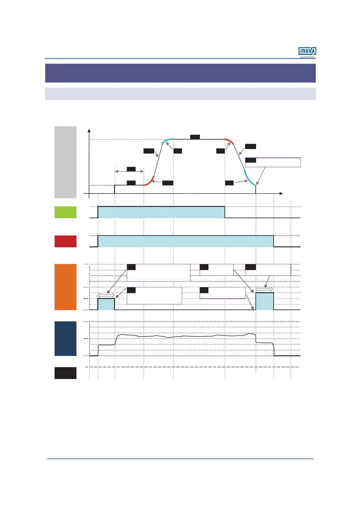
9 Complete Timing Diagram
F0-08
[x.x Hz]
F0-18
F0-17 F6-09 F6-08 [x.x Sec]
[x.x Sec] [x.x% ] [x.x% ]
F6-11
DC injection braking 2 frequency threshold
F6-04
[x.x Sec]
F6-03 F6-08 F6-09
[x.x Hz] [x.x% ] [x.x% ]
0
F6-06 [ x.x Sec]: F6-13 [ x % ]: F6-14 [ x.x Sec]:
DC injection braking 1 active time(if F6-00=0) DC injjection braking 2 level DC injection braking 2 active time
Pre-excitation active time (if F6-00=2)
F6-05 [ x % ]: F6-12 [ x.x Sec] (default: 0.0 Sec)
DC injection braking 1 level (if F6-00=0) DC injection braking 2 delay time
Pre-excitation level (if F6-00=2)
t1
Time
DI 1
Forward
IGBT's Ac tive
Frequency
Frequency
output
command
[ x.x Hz]: default 0.0 Hz
t9
ON
OFF
ON
OFF
t2
t4
t5
t6
t7
t8
t3
0%
DC Injection/
Pr e-excitation
Motor Current
20%
40%
Stages
100%
100%
50%
0%
efesotomasyon.com

Questions and Answers:

Question and Answer IconNeed help?

Do you have a question about the Inovance MD210 Series and is the answer not in the manual?

Inovance MD210 Series Specifications

General IconGeneral
BrandInovance
ModelMD210 Series
CategoryInverter
LanguageEnglish

Related product manuals