Parameter Description MD280/MD280N User Manual
- 138 -
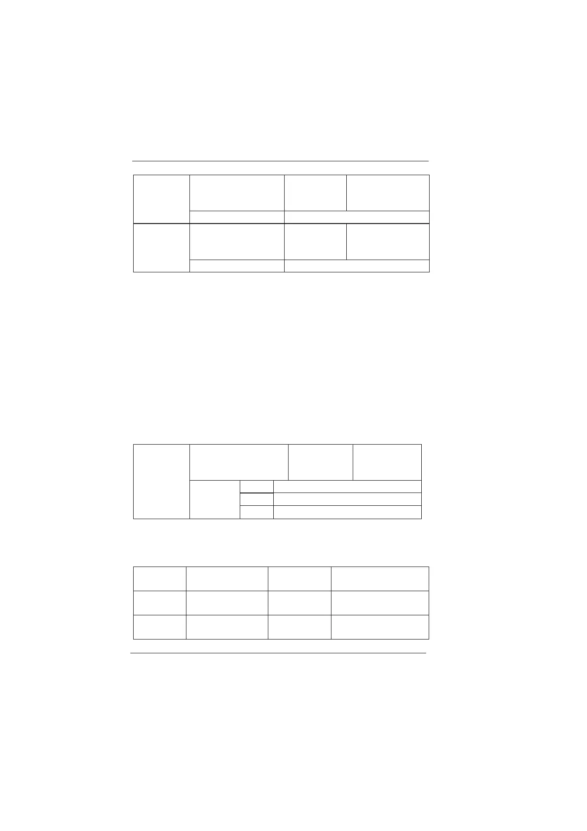
AI1 is used as the
function selection of
DI6
Factory
default value
0
F2-27
Setup range The same as F2-00
AI2 is used as the
function selection
of DI7
Factory
default value
0
F2-28
Setup range The same as F2-00
AI is used as DI, but the ground of AI (GND) and DI (COM) are not to
breakover.
Group F3 Output Terminal
MD280 series inverter provides one multifunctional terminal output
selection (FMP, AO or DO3), one multifunctional relay output terminal
(RELAY) and two multifunctional digital output terminal (DO1 and DO2).
FM and AO terminals are two different types of signal output terminals in
the same channel and cannot be used at the same time. FM terminal has
two-type of functions and can select output PULSE signal (FMP) or digital
signal (DO3). The output signal type can be selected via F3-00.
Remark: FMP pulse signal and DO3 digital signal are all output via FM
terminal.
Multifunctional
terminal output
selection
Factory
default value
2
0 FM (FMP pulse output)
1 FM (DO3 digital output)
F3-00
Setup
range
2
AO (Analog output)
Caution: The “PULSE setup (DI5)” function of the frequency source (F0-01)
and the “FMP pulse output” function of the FM terminal (F3-00) cannot be
selected for use at the same time.
F3-01
RELAY output
selection
Factory
default value
2 (Fault output)
F3-02
DO1 output
selection
Factory
default value
1( Inverter being
running)
F3-03
DO2 output
selection
Factory
default value
4( Frequency arrival)
efesotomasyon.com
 Loading...
