Parameter Description MD280/MD280N User Manual
- 142 -
Maximum frequency of
FMP output
Factory
default
value
50.0kHz
F3-08
Setup range 0.1kHz to 50.0kHz
When the multifunctional terminal output function (F3-00) selects FMP
pulse output, it can set the maximum frequency value of output pulse.
F3-09
RELAY output delay
time
Factory
default value
0.0s
F3-10
DO1 output delay
time
Factory
default value
0.0s
F3-11
DO2 output delay
time
Factory
default value
0.0s
DO3 output delay
time
Factory
default value
0.0s
F3-12
Setup range 0.0s to 3600.0s
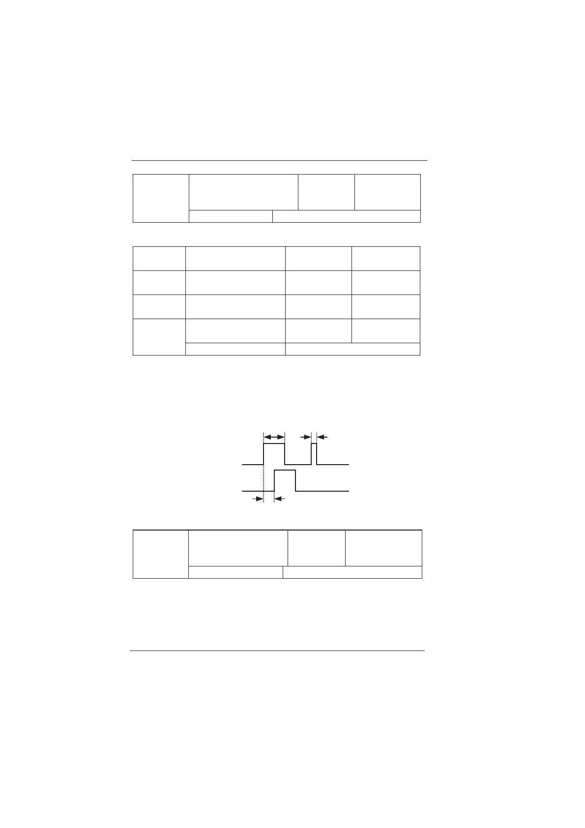
These functions mean that DOx signal (including RELAY) to maintain a
valid pulse hold time, as shown in Figure 6-10. Only when DOx signal is
greater than the width of the function code in order to be identified,
1w
t in
the diagram can be identified,
2w
t is ignored.
Signal length
Signal length
1w
t
2w
t
DOx output delay time
i
nal before
time-delay
i
nal after
ime-delay
Schematic Diagram for DOx output delay time
DO output terminal
valid state selection
Factory
default
value
0
F3-13
Setup range 0 to 15
Set the valid state of DI input terminal by bits.
0: Positive logic (Valid connected)
1: Antilogical (Invalid disconnected)
The corresponding relationship between BIT and DI is shown as the
following table:
efesotomasyon.com
 Loading...
