MD280/MD280N User Manual Mechanical and Electrical Installation
- 47 -
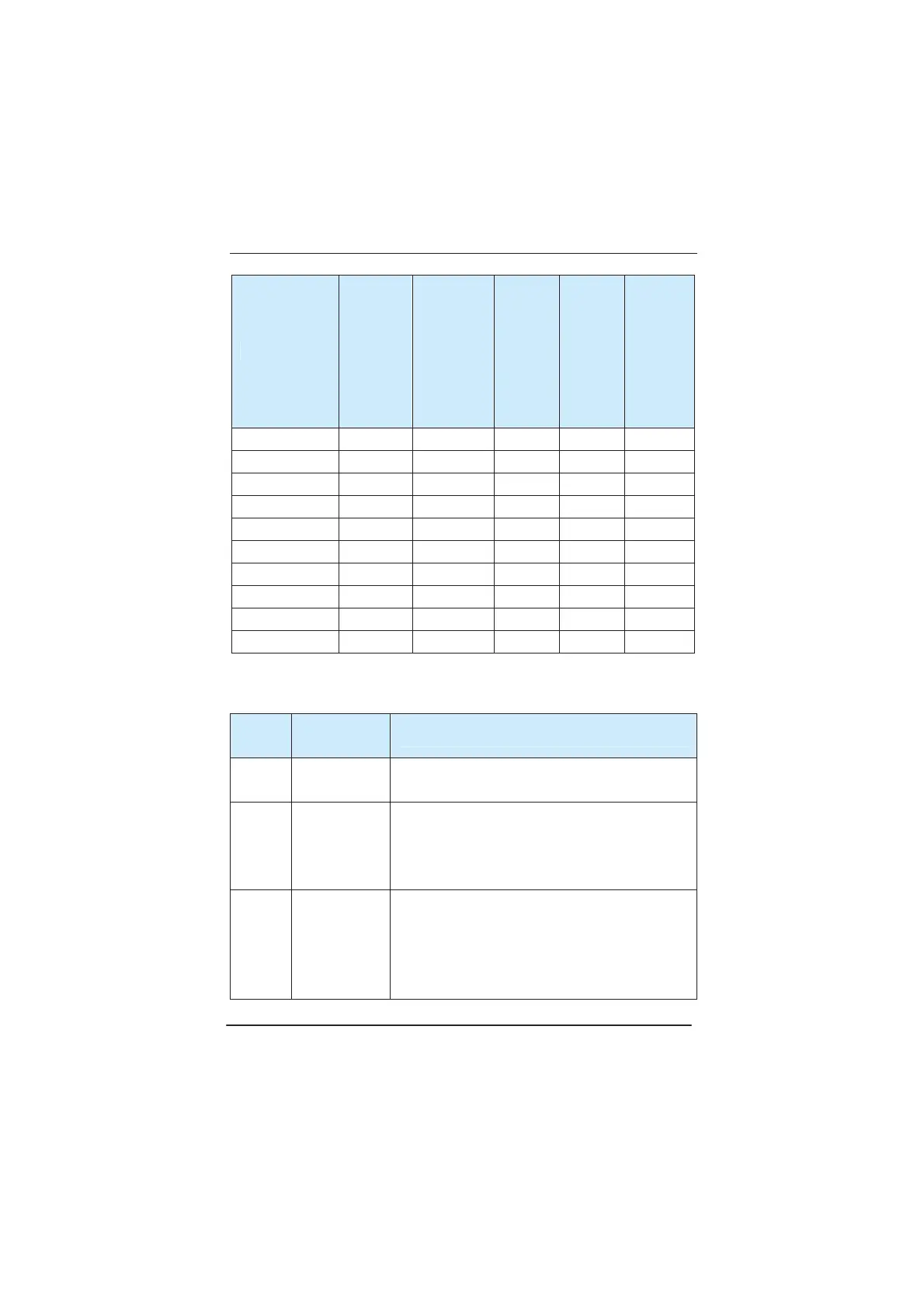
Inverter Model
Circuit
Breaker
(MCCB)
(A)
Recommend
ed Contactor
(A)
Recomme
nded
Input
Side Main
Circuit
Wire
(mm²)
Recomme
nded
Output
Side Main
Circuit
Wire
(mm²)
Recomme
nded
Control
Circuit
Wire (mm²)
MD280T110G/132P 400 400 150 150 1.5
MD280T132G/160P 500 400 185 185 1.5
MD280T160G/200P 600 600 150*2 150*2 1.5
MD280T200G/220P 600 600 150*2 150*2 1.5
MD280T220G/250P
800 600 185*2 185*2 1.5
MD280T250G/280P
800 800 185*2 185*2 1.5
MD280T280G/315P
800 800 150*3 150*3 1.5
MD280T315G/355P
800 800 150*4 150*4 1.5
MD280T355G/400P
1000 1000 150*4 150*4 1.5
MD280T400G/450P
1000 1000 150*4 150*4 1.5
3.2.2 Use instruction of peripheral electric parts:
Table 3-2 Guide to the Use Instruction of Peripheral Electric Parts of MD280 Inverter
Part
Name
Installation
Location
Function Description
Circuit
breaker
The front-end of
the input circuit
Disconnect the power supply in case of downstream equipment
is over current.
Contactor
Between the
circuit breaker
and the inverter
input side
Power-on and power-off of the inverter.Frequent
power-on/power-off operation on the inverter shall be avoided.
AC input
reactor
Input side of the
inverter
1˅ Improve the power factor of the input side.
2˅ Eliminate the high order harmonics of the input side
effectively, and prevent other equipment from damaging
due to voltage waveform deformation.
3˅ Eliminate the input current unbalance due to the
efesotomasyon.com
 Loading...
