6. Description of Parameters
- 163 -
6
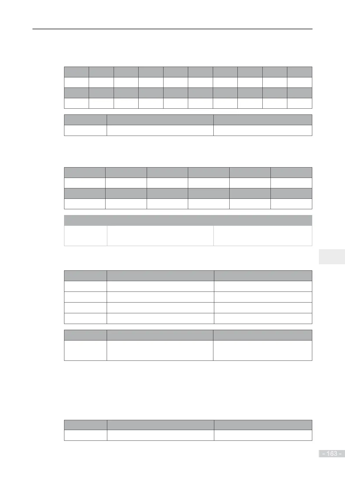
U0-07: It displays state of DI terminals. After the value is converted into a binary number, each
bit corresponds to a DI. “1” indicates high level signal, and “0” indicates low level signal. The
corresponding relationship between bits and DIs is described in the following table:
Bit0 Bit1 Bit2 Bit3 Bit4 Bit5 Bit6 Bit7 Bit8 Bit9
DI1 DI2 DI3 DI4 DI5 DI6 DI7 DI8 DI9 DI10
Bit10 Bit11 Bit12 Bit13 Bit10 Bit11 Bit12 Bit13 Bit14 Bit15
VDI1 VDI2 VDI3 VDI4 VDI1 VDI2 VDI3 VDI4 VDI5 -
Function Code Parameter Name Display Range
U0-08
DO state 0 to 1023
U0-08: It displays state of DO terminals. After the value is converted into a binary number, each
bit corresponds to a DO. "1" indicates high level signal, and "0" indicates low level signal. The
corresponding relationship between bits and DOs is described in the following table.
Bit0 Bit1 Bit2 Bit3 Bit4 Bit5
DO3 Relay 1 Relay 2 DO1 DO2 VDO1
Bit6 Bit7 Bit8 Bit9 Bit10 Bit11
VDO2 VDO3 VDO4 VDO5 - -
Function Code Parameter Name Display Range
U0-10
AI2 voltage (V)/current (mA) 0.00 to 10.57 V
0.00 to 20.00 mA
U0-10: Whether AI2 receives voltage input or current input is determined by setting of jumper J9
on the control board.
Function Code Parameter Name Display Range
U0-14
Load speed display 0 to rated motor speed
U0-15
PID reference 0 to 65535
U0-16
PID feedback 0 to 65535
U0-18
Pulse reference 0.00 to 100.00 kHz
Function Code Parameter Name Display Range
U0-19
Feedback speed -320.00 to 320.00 Hz
-500.0 to 500.0 Hz
U0-19: It displays actual output frequency of the AC drive.
The tens position of F7-12 (Number of decimal places for load speed display) determines the
number of decimal places of U0-19.
Ɣ
If the tens position is set to 2, the display range is -320.00 to 320.00 Hz.
Ɣ If the tens position is set to 1, the display range is -500.0 to 500.0 Hz.
Function Code Parameter Name Display Range
U0-20
Remaining running time 0.0 to 6500.0 min
U0-20: It displays remaining running time during drive timing running.
 Loading...
