6. Description of Parameters
- 162 -
6
Function Code Parameter Name Setting Range Default
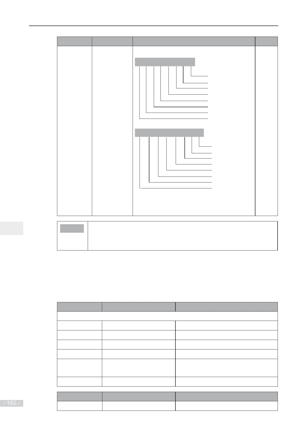
F7-05
LED display stop
parameters
0000 to FFFF
7 6 5 4 3 2 1 0
Bus voltage (V)
DO state
AI1 voltage (V)
Count value
Frequency reference (Hz)
DI state
AI2 voltage (V)
AI3 voltage (V)
15 14 12 11 10
9 8
PLC stage
Pulse reference (kHz)
Length value
Reserved
13
Load speed
PID reference
Reserved
Reserved
If a parameter needs to be displayed during
running, set corresponding bit to 1, and set F7-05 to
hexadecimal equivalent.
1F
Note
Ɣ
Once the AC drive is re-powered on after power down, the display includes the
selected parameters before power down by default.
Ɣ
If parameters to be monitored cannot be found in F7-03, F7-04 and F7-05, view
them in group U0.
Ƶ
View Parameters in Group U0
You can view parameter values by using operation panel, convenient for on-site commissioning,
or from the host computer by means of communication (address: 0x7000-0x7044).
8WR8DUHWKHPRQLWRULQJSDUDPHWHUVLQWKHUXQQLQJDQGVWRSVWDWXVGH¿QHGE\)
and F7-04.
Function Code Parameter Name Display Range
Group U0: Monitoring Parameters
U0-00
Running frequency
0.00 to 500.00 Hz
U0-01
Frequency reference
0.00 to 500.0 Hz
U0-02
Bus voltage 0.0 to 3000.0 V
U0-03
Output voltage 0 to 1140 V
U0-04
Output current WR$$&GULYHSRZHUN:
0.0 to 6553.5 A (AC drive power > 55 kW)
U0-05
Output power 0 to 32767
Function Code Parameter Name Display Range
U0-07
DI state 0 to 32767
 Loading...
