Electrical Installation
‑41‑
R S T
POWER
U V W
MOTOR
BR (+) (-)
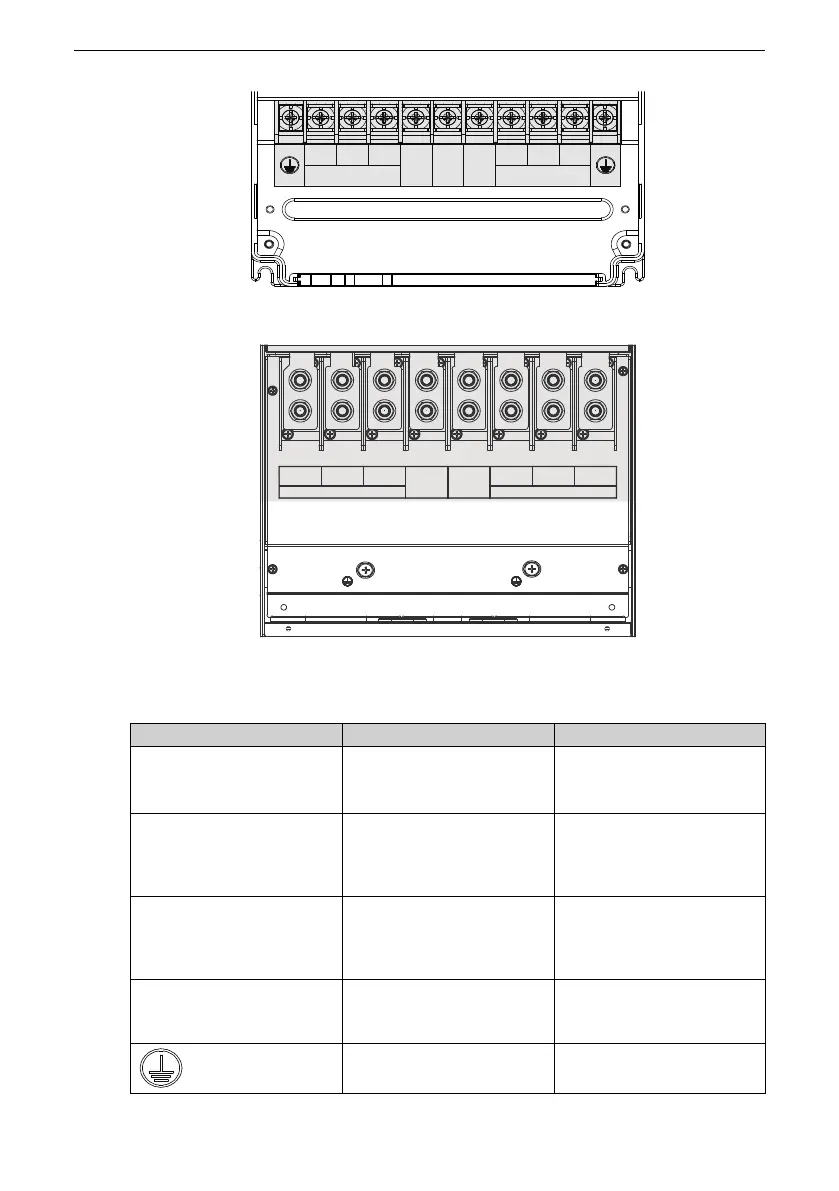
Figure 2‑5 Layout of main circuit terminals for T5 to T8 models
Figure 2‑6 Layout of main circuit terminals for T9 models
Table 2–1 Descriptions of main circuit terminals
Terminal Identification
Name
Function
R, S, T
Three‑phase power supply
input terminals
The terminals are used to
connect the three‑phase AC
power supply.
(+), (‑)
Positive and negative
terminals of the DC bus
Common DC busbar input;
connected to the external
braking unit of T9 models
and above.
(+), BR
Braking resistor connection
terminals
The terminals are used to
connect to the braking
resistor of T8 models and
below.
U, V, W
Output terminals The terminals are used to
connect to a three‑phase
motor.
Grounding terminal (PE) It is used for protective
grounding.

 Loading...


