Chapter: Assemble the load string
80 M10-17313-EN
Install a 2530 load cell (capacities 5 N through 5 kN)
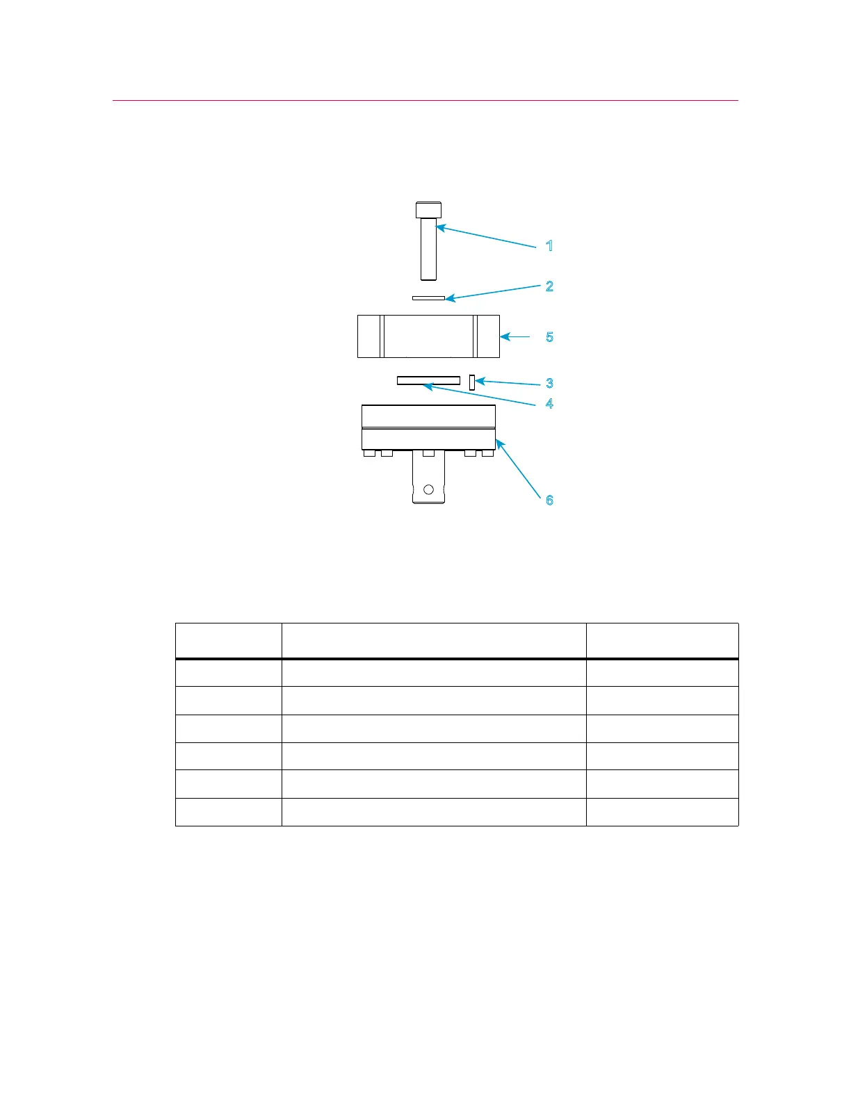
Figure 17. Install a 2530 series load cell - capacities 5 N through 5 kN
Legend for Figure 17
1. Refer to Figure 17 on page 80 and its associated legend.
2. Collect together the correct mounting screw, washer, anti-rotation pin and locating
ring for your combination of load frame and load cell.
3. Assemble the mounting screw and washer, as shown in the figure.
4. Place the mounting screw and washer assembly into the top of the central bore of the
crosshead.
Label Component Part number
1 Screw, M10 x 40 201V57
2M10 load washer 610J9
3 Load cell anti-rotation pin 705K84
4 Locating ring T1335-1048
5Crosshead
6 2530 load cell - 5 N through 5 kN

 Loading...


