1-5
System Components and Interconnections
Product Support: www.instron.com
System Components and Interconnections
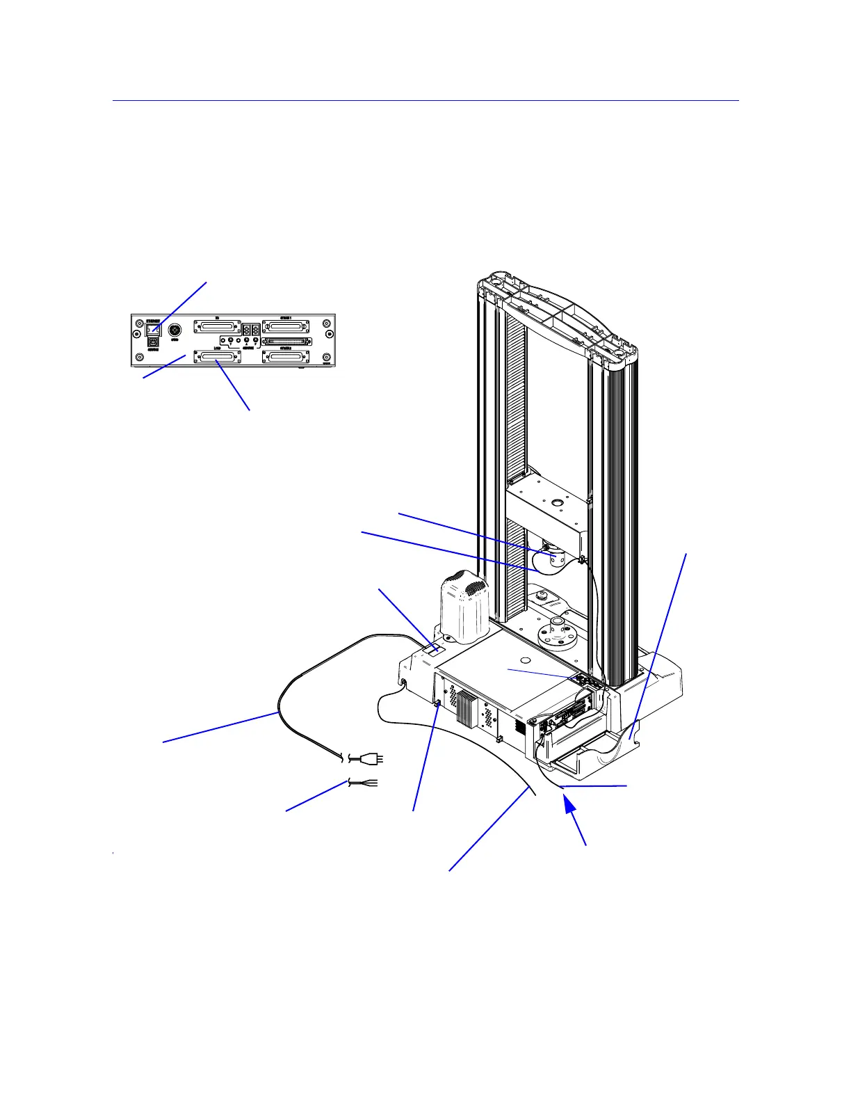
Figure 1-1 on page 1-2 shows you how each hardware component is connected to make up
the complete testing system.
Figure 1-2. 5960 System Connections
Ethernet
crossover cable
Computer interface
connection
Load cell cable
Mains power cable
GRN/YEL - Earth
BRN - Live
BLU - Neutral
Ground stud
Load cell
Controller
cover
Computer interface
connection
Load cell connection
Controller
Supplemental ground
cable
System ID label
Options
panel