4-5
Connect the System Components
Product Support: www.instron.com
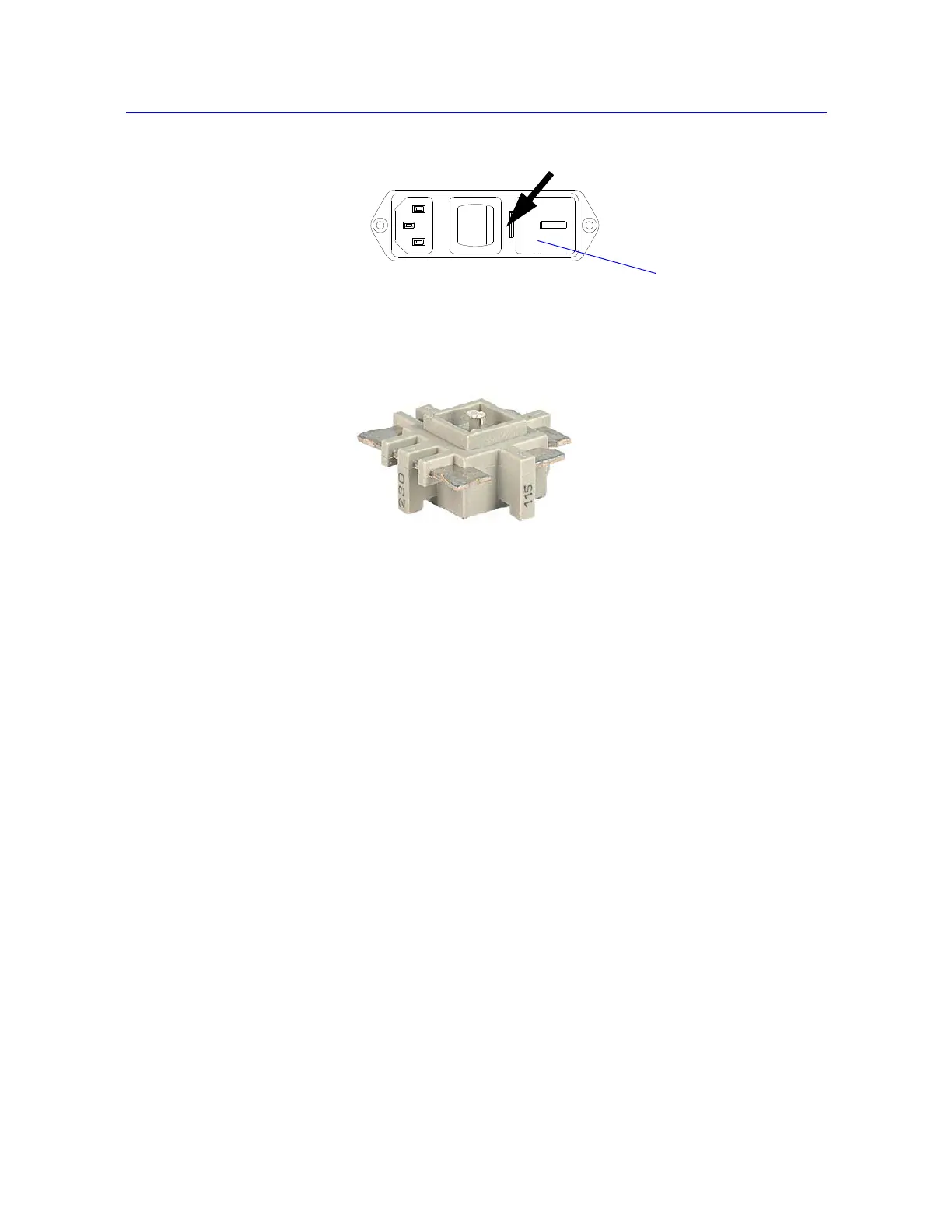
5. Re-insert the voltage selector unit in the power input connector so that the required
voltage faces the front.
6. If necessary, change the fuse in the holder. Refer to “Replace a Fuse” on page 5-7 for
replacing a fuse.
7. Re-install the fuse holder into the connector. Ensure that the indicator now indicates the
correct input voltage.
8. Re-connect the power cable to the main power source and turn on the system. Verify that
the
POWER indicator light illuminates.
9. Before you do any testing, perform the procedure “First Time Startup” on page 4-11.
Connect the System Components
The following procedure describes the connections for the basic components of an Instron
electromechanical system. If you purchased additional accessories for your system, you
need to refer to the documentation for those accessories for proper installation.
Figure 4-3. Prying out the fuse holder
Figure 4-4. Voltage Selector Unit