Connections
En-18
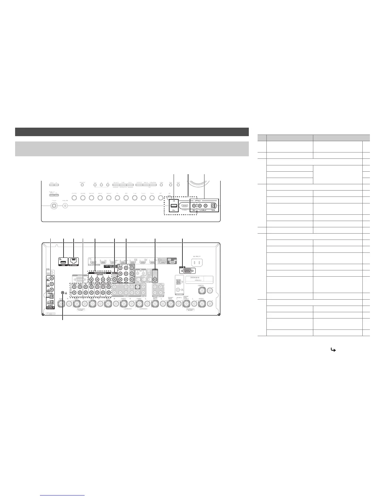
Connect your components to the appropriate jacks. The default input assignments are shown below. See “Connection Tips
and Video Signal Path” for more information (➔ page 100).
Connecting Your Components
The on-screen menus appear only on a TV that is connected to HDMI OUT MAIN. If your TV is connected to other
video outputs, use the AV receiver’s display when changing settings.
C
BA
D A E GF H I KJ
Front
Rear
GND screw
✔: Assignment can be changed (➔ pages 56, 57).
No. Jack/Port Components
A
USB
*1*2
iPod/iPhone, MP3 player,
USB flash drive
B
USB, AUX Input Video
*3
iPod/iPhone (video playback)
C
AUX Input
Video Camcorder, etc
Audio L/R
Digital
D
DIGITAL IN
COAXIAL 1 (BD/DVD) Blu-ray Disc/DVD player ✔
COAXIAL 2 (CBL/SAT)
Satellite/cable set-top box, etc.
✔
COAXIAL 3 (STB/DVR) Set top box/digital video
recorder, etc
✔
OPTICAL 1 (GAME 1) Game consoles ✔
OPTICAL 2 (TV/CD) TV, CD player ✔
E
ETHERNET Router
F
AUDIO IN
BD/DVD IN Blu-ray Disc/DVD player
CBL/SAT IN
Satellite/cable set-top box, etc.
STB/DVR IN Set top box/digital video
recorder, etc
GAME 1 IN Game console, RI dock
PC IN Personal computer
TV/CD IN TV, CD player, cassette
tape deck, MD, CD-R,
Turntable
*4
, RI dock
PHONO IN
Turntable
*4
G
VIDEO IN
IN 1 (BD/DVD) Blu-ray Disc/DVD player ✔
IN 2 (CBL/SAT)
Satellite/cable set-top box, etc.
✔
IN 3 (STB/DVR) Set top box/digital video
recorder, etc
✔
IN 4 (GAME 1) Game console, RI dock ✔
To be continued