PCI Express* Add-in Card Considerations
336521 25
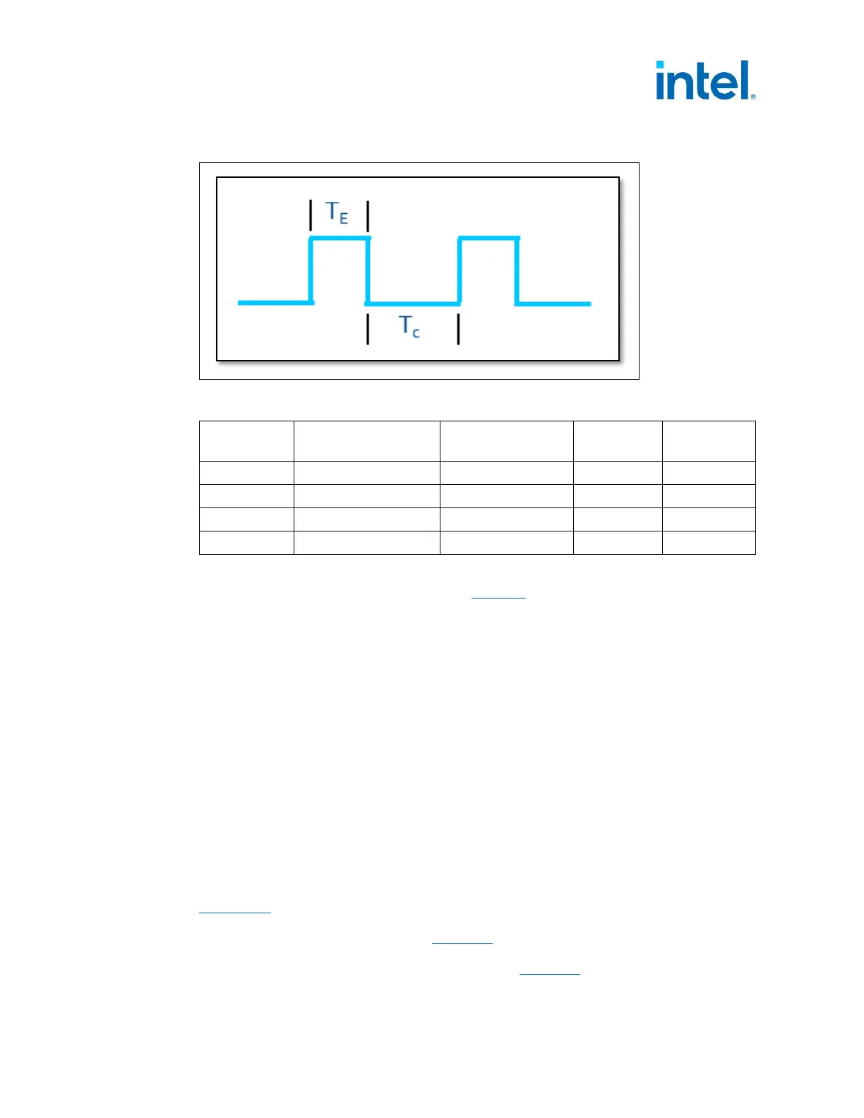
Figure 3-2: Duty Cycle Definition
Table 3-4: Duty Cycle Example Test Criteria for a 1000W PSU – RMS
Duty Cycle
Time for Power
Excursion (T
E
)
Time Constant
(T
C
)
Power @
T
E
Power
@ T
C
10% 100 µs 900 µs 2000 W 817 W
20% 1 ms 4 ms 1800 W 663 W
25% 10 ms 30 ms 1600 W 693 W
50% 100 ms 100 ms 1200 W 749 W
NOTES:
1. The Capacitive Load mentioned in Table 4-7
is expected to be applied to this test
scenario.
2. Total Test time for each Power Excursion testing time is expected to last until
thermal saturation occurs in the PSU.
3. More details about test time for each row above and formulas to calculate T
C
and T
E
power values for different PSU sizes will be detailed in the “Desktop Platform Form
Factor Power Supply Test Plan – Doc #338448
3.2 PCIe* AIC Auxiliary Power Connectors
The PCIe CEM 5.0 specification defines three 12V Auxiliary Power Connectors to be
used with PCIe Add-in Cards
1. 75 W 2x3 connector
0. 150 W 2x4 connector
1. 600 W 2x6 12VHPWR connector (new in PCIe 5.0)
Section 5.2
specifies the Mechanical information for all DC Power Connectors. Note
that the Voltage Tolerance listed below is different from this Power Supply Design
Guide for the Low voltage tolerance
Table 4-2, the reason for the difference is allowing
for voltage drop on a motherboard from the Main Power Connector to the
motherboard to the PCIe* Edge Card Connector.
Table 3-5 shows the voltage