Electrical
32 336521
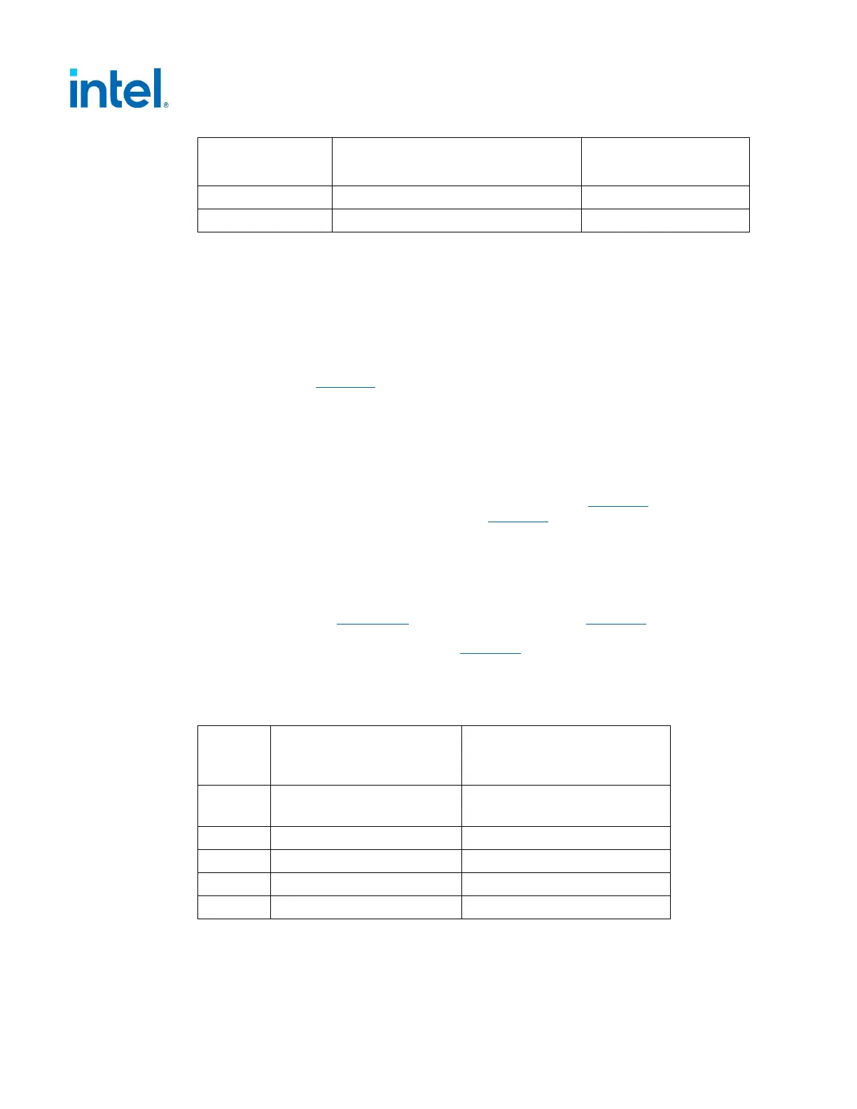
Output
Maximum Step Size
(% of rated output amps)
Maximum Step Size
(A)
-12VDC - 0.1
+5VSB - 0.5
NOTES:
1. Example of how to use this table, for a rated +5 VDC output of 14A, the transient step
would be 30% x 14 A = 4.2 A. Testing for a 4.2 A step size would result in testing
starting at 9.8A going up to 14A.
2. 12V2 rails are typically used for CPU power. CPU step size will have more updated
values in the Power Supply Design Guide Addendum (# 621484) which will be used to
determine the 85% value
3. 12V3/V4 rails are typically used for PCIe* Add-in Card connectors. This recommendation
is based on Chapter 3 where PCIe* Add-in Card needs are discussed. The step size will
come from the amount of PCIe* Add-in Card power supported based on the size of the
PSU in
Table 3-2.For more detail reference the Desktop Platform Form Factor Power
Supply Test Plan (Doc # 338448)
4. Power supplies that have one combined 12V rail shall perform Dynamic testing on the
one 12V rail with multiple tests which simulate different system level workloads: 12V1
(total system), 12V2 (CPU Load), and 12V3/V4 (PCIe AIC).
Output voltages should remain within the regulation limits of Table 4-2, for
instantaneous changes in load as specified in Table 4-3 and for the following
conditions:
• Simultaneous load steps on the +12 VDC, +5 VDC, and +3.3 VDC outputs (all steps
occurring in the same direction)
• Load-changing repetition rate of 50 Hz to 10 kHz
• AC input range per Section 2.1 and Capacitive loading per Table 4-7
The transient load slew rate is defined in Table 4-5 based on whether the PSU
supports the PCIe* 12VHPWR Connectors. This usually can be correlated to the PSU’s
Rated Wattage, which is listed as a guidance.
Table 4-4: DC Output Transient Slew Rate
Output
PSU without PCIe*
12VHPWR Connectors
(Rated Size ≤450 Watts)
PSU with PCIe*
12VHPWR Connector
(Rated Size >450 Watts)
All
+12V
2.5 A/µs 5.0 A/µs
+5V 1.0 A/µs 1.0 A/µs
+3.3V 1.0 A/µs 1.0 A/µs
+5VSB 0.1 A/µs 0.1 A/µs
-12V 0.1 A/µs 0.1 A/µs