Mechanical
56 336521
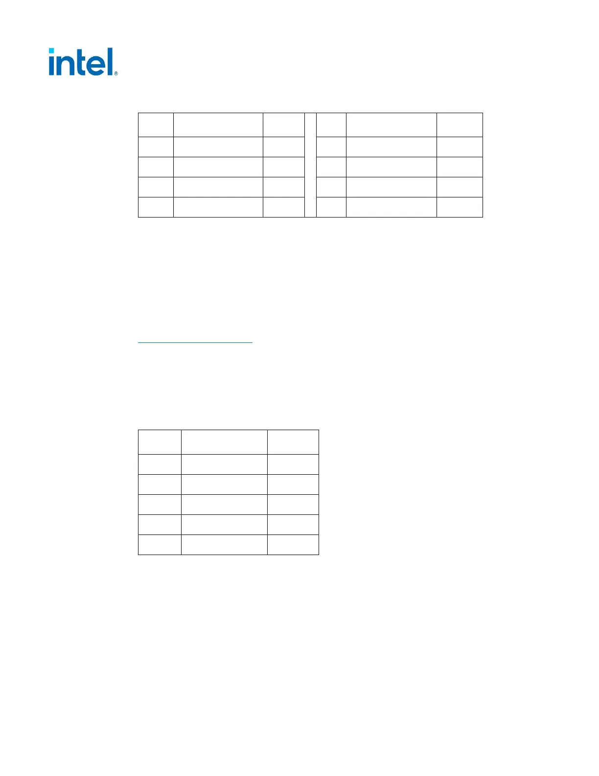
Table 5-9: +12 V Power 8 pin Connector Pin-Out
Pin Signal Color
1
Pin Signal Color
1
1
COM Black
5
+12V2 DC Yellow
2
COM Black
6
+12V2 DC Yellow
3
COM Black
7
+12V2 DC Yellow
4
COM Black
8
+12V2 DC Yellow
NOTE: 18 AWG wire.
5.2.2.6 Serial ATA* Connectors – REQUIRED
This is a required connector for systems with Serial ATA devices.
The detailed requirements for the Serial ATA Power Connector can be found in the
“Serial ATA: High Speed Serialized AT Attachment” specification, Section 6.3 “Cables
and connector specification”.
http://www.serialata.org/
Note: Connector pin numbers and wire numbers are not 1:1. Carefully check to confirm the
correct arrangement.
Assembly: Molex* 88751 or equivalent.
Table 5-10: Serial ATA* Power Connector Pin-out
Wire Signal Color
1
5
+3.3V DC Orange
2
4
COM Black
3
+5V DC Red
2
COM Black
1
+12V1 DC Yellow
NOTES:
1. 18 AWG wire.
2. +3.3V DC is removed from SATA V3.2 spec. but it is recommended if there is backward
compatibility concern.