Mechanical
336521 55
• Signal Pin Contact Plating: Tin plated on contact area
• All dimensions are in mm
• Connector must be compatible with lead-free soldering process.
Wire Details:
• Power/Ground Pin Wire Size: 16 AWG
All 12 pins must be connected to the power supply using 16 AWG cable
• Sideband Signals Pin Wire Size: 28 AWG
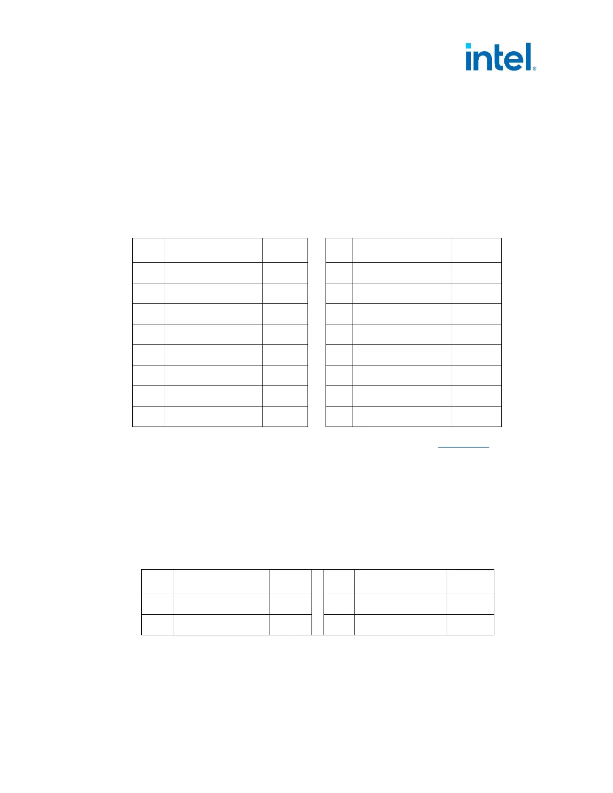
Table 5-7: PCIe* 12VHPWR Auxiliary Power Connector Pin Assignment (600 Watts)
Pin Signal Color
1
Pin Signal Color
1
1
+12V3/V4 Yellow
7
COM Black
2
+12V3/V4 Yellow
8
COM Black
3
+12V3/V4 Yellow
9
COM Black
4
+12V3/V4
Yellow
10
COM
Black
5
+12V3/V4
Yellow
11
COM
Black
6
+12V3/V4
Yellow
12
COM
Black
S1
CARD_PWR_STABLE Blue
S3
SENSE0 Blue
S2
CARD_CBL_PRES# Blue
S4
SENSE1 Blue
The electrical function for the sideband pins S1- S4 is detailed in Section 3.3 of this
document.
5.2.2.5 +12 V Power Connector
Connector: Molex* 0039012040 or equivalent.
Contact: Molex 44476-1112 (HCS) or equivalent (Mating motherboard connector is
Molex 39-29-9042 or equivalent).
Table 5-8: +12 V Power 4 pin Connector Pin-out
Pin Signal Color
1
Pin Signal Color
1
1
COM Black
3
+12V2 DC Yellow
2
COM Black
4
+12V2 DC Yellow
NOTE: 18 AWG wire.