PCI Express* Add-in Card Considerations
336521 29
0/1 sideband signals. If this feature is used and the SENSE 0/1 signals are
dynamically changed they must be changed only when the power supply is in Standby
Mode (PS_ON# is de-asserted and Main Power rails are not on). Once PS_ON# and
the main power rails achieve their full voltages the SENSE 0/1 sideband signals must
not be changed.
An example for this scenario would be if a power supply has enough rated power to
supply 600 Watts to one PCIe* Add-in Card it could determine the following scenarios:
• One PCIe* Add-in Card is detected, and that one card gets 600 Watt.
• Two PCIe* Add-in Cards are detected, each card gets 300 Watts.
• Three or Four PCIe* Add-in Cards are detected, each card gets 150 Watts.
3.3.4 Sideband Signals DC Specifications (Required)
The four sideband signals defined for the 12VHPWR connector DC Specifications are
shown in Table 3-7
. This is the requirement defined by the PCIe* CEM 5.0
Specification for the Add-in Cards.
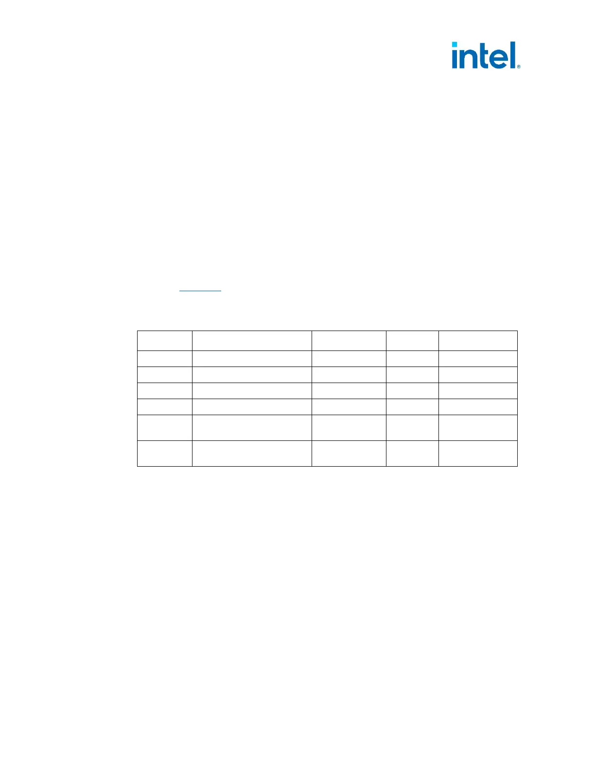
Table 3-7: PCI Express* 12VHPWR Connector – Sideband Signal DC Specifications
Symbol Parameter Conditions Min Max
V
HMAX
Max High Voltage any Pin
3.3 V +0.5 V
V
IL
Input Low Voltage -0.2 V +0.8 V
V
IH
Input High Voltage
+2.0 V 3.3 V +0.2 V
V
OL
Output Low Voltage 7.0 mA -0.2 V +0.5 V
V
OH
Output High Voltage (refer
note)
4.0 mA +2.4 V 3.3 V + 0.2 V
R
PULL-UP
Pull-up / Pull-down
Resistance tolerance
-10% +10%
NOTE: For Open-Collector/Open Drain Signal CARD_PWR_STABLE output a pull-up is required.
There is no VOH specification for this signal.
§§