Intel Desktop Board D2500CC Product Guide
34
Front Panel Audio Header
Figure 12, A shows the location of the front panel audio header. The front panel audio
header can be used for both Intel HD Audio and AC ‘97 Audio.
Table 5 shows the pin assignments f
or the Intel HD Audio and Table 6 shows the pin
assignments for AC ‘97 Audio.
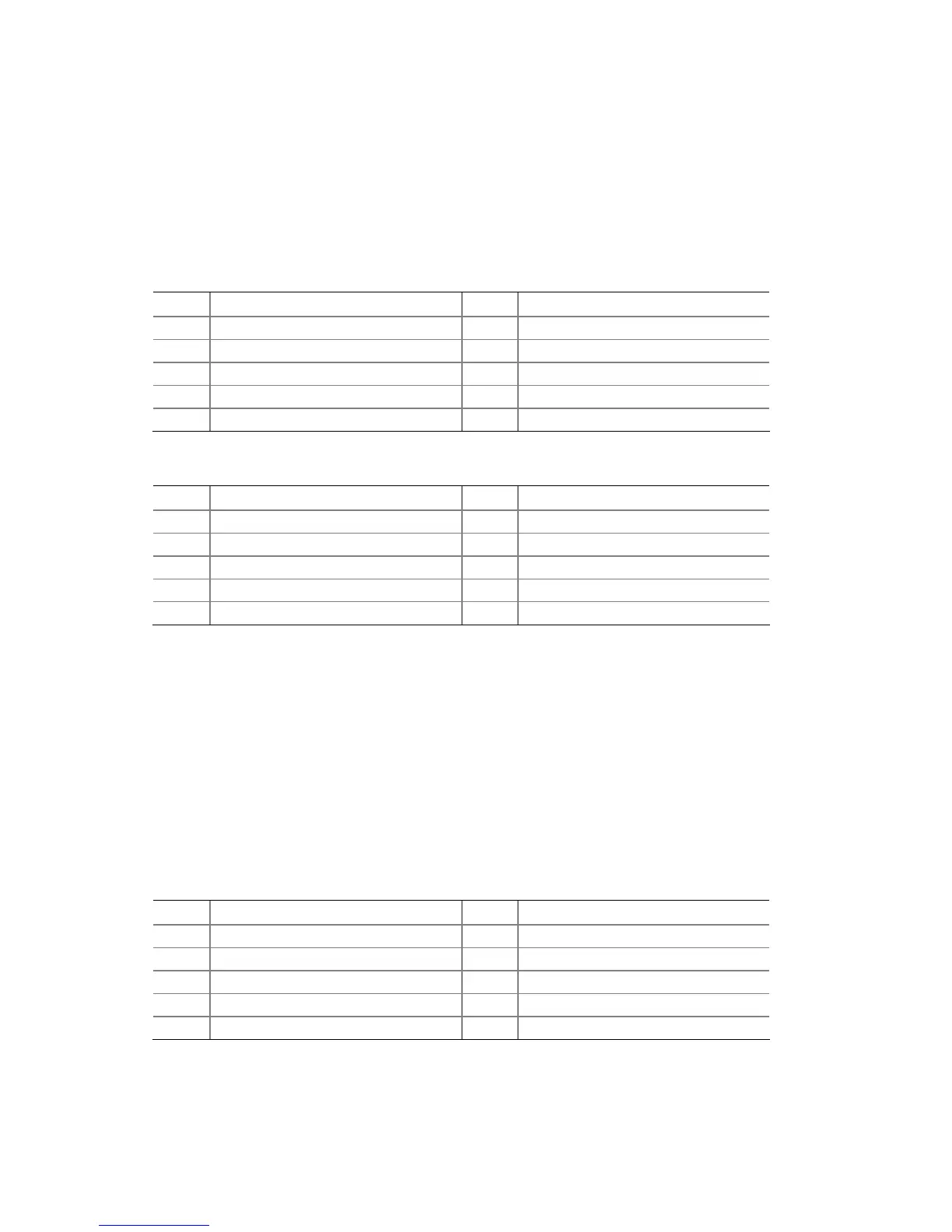
Table 5. Front Panel Audio Header for Intel HD Audio
Pin Signal Name Pin Signal Name
1 [Port 1] Left channel 2 Ground
3 [Port 1] Right channel 4 PRESENCE# (Dongle present)
5 [Port 2] Right channel 6 [Port 1] SENSE_RETURN
7 SENSE_SEND (Jack detection) 8 Key (no pin)
9 [Port 2] Left channel 10 [Port 2] SENSE_RETURN
Table 6. Front Panel Audio Header for AC ‘97 Audio
Pin Signal Name Pin Signal Name
1 MIC 2 AUD_GND
3 MIC_BIAS 4 AUD_GND
5 FP_OUT_R 6 FP_RETURN_R
7 AUD_5V 8 KEY (no pin)
9 FP_OUT_L 10 FP_RETURN_L
Front Panel USB 2.0 Headers
Before connecting to the USB headers, observe the precautions in "Before You Begin"
on page 23. See Figure 12, B and G for the location of the USB 2.0
headers. Table 7
and Table 8 show the pin assignments for the headers.
The brown
USB header (Figure 12, B) provides a single USB port while
the black USB
header (Figure 12, G) provides two USB ports. The singl
e USB port header is designed
to support a Flash Memory Drive such as the Intel Z-U130 USB Solid-State Drive (or
compatible device). Refer to “Installing an Intel
®
Z-U130 USB Solid-State Drive or
Compatible Device” on page 32 for more information.
Table 7.
Front Panel USB Header
Pin Signal Name Pin Signal Name
1
+5 VDC
2
+5 VDC
3
D-
4
D-
5
D+
6
D+
7
Ground
8
Ground
9
KEY (no pin)
10
No Connect