Installing and Replacing Desktop Board Components
35
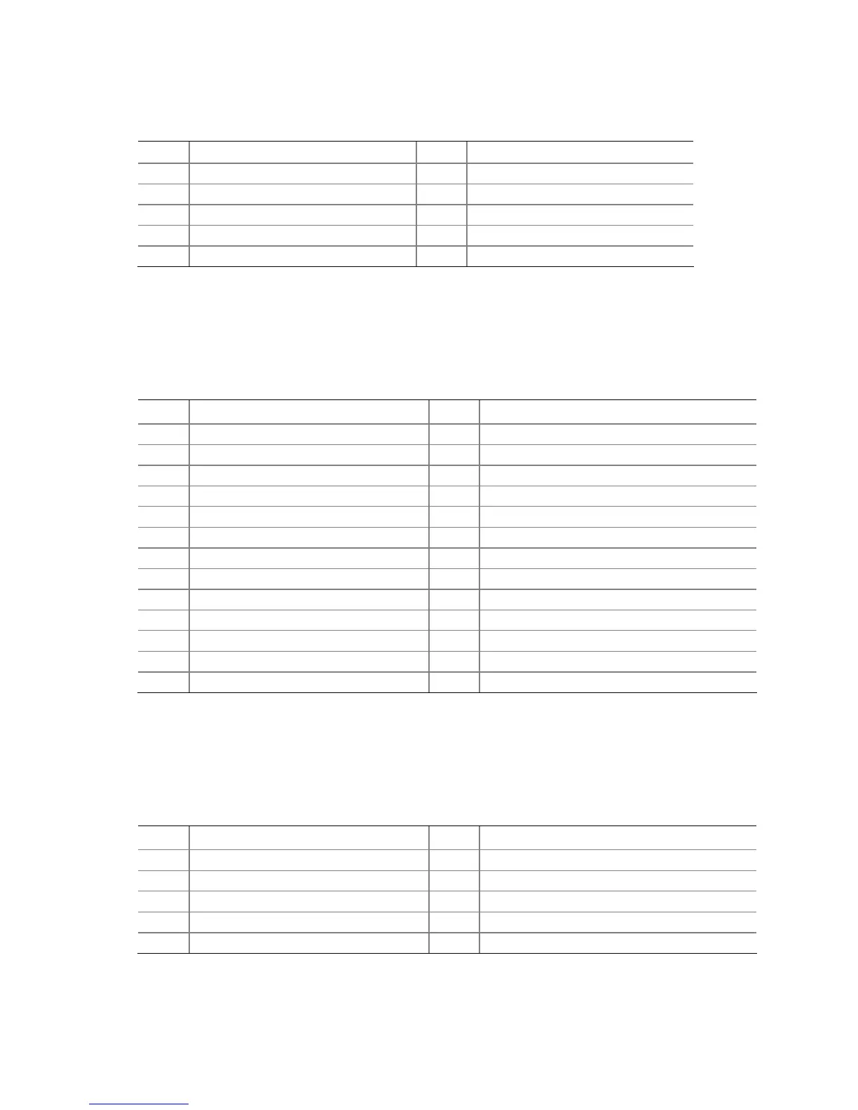
Table 8. Front Panel USB Header with Intel Z-U130 USB Solid-State Drive or
Compatible Device Support
Pin Signal Name Pin Signal Name
1
+5 VDC
2
No Connect
3
D-
4
No Connect
5
D+
6
No Connect
7
Ground
8
No Connect
9
KEY (no pin)
10
LED#
Parallel Port Header
Figure 12, C shows the location of the port header. Table 9 shows the pin
assignments and signal names for the parallel port header.
Table 9. Parallel Port Header
Pin Signal Name Pin Signal Name
1 STROBE# 2 AUTOFD#
3 PD0 4 PERROR
5 PD1 6 INT#
7 PD2 8 SLCTIN#
9 PD3 10 Ground
11 PD4 12 Ground
13 PD5 14 Ground
15 PD6 16 Ground
17 PD7 18 Ground
19 ACK# 20 Ground
21 BUSY 22 Ground
23 FAULT# 24 Ground
25 SELECT 26 Key (no pin)
Serial Port Headers
Figure 12, D shows the location of the serial headers. Table 10 shows the pin
assignments and signal names for each serial header.
Table 10. Serial Port Header
Pin Signal Name Pin Signal Name
1 DCD (Data Carrier Detect) 2 RXD# (Receive Data)
3 TXD# (Transmit Data) 4 DTR (Data Terminal Ready)
5 Ground 6 DSR (Data Set Ready)
7 RTS (Request To Send) 8 CTS (Clear To Send)
9 RI (Ring Indicator) 10 Key (no pin)