Contents
vii
B Regulatory Compliance
Safety Regulations ..............................................................................................................69
Place Battery Marking ................................................................................................69
European Union Declaration of Conformity Statement ........................................................70
Product Ecology Statements ...............................................................................................71
Lead-Free Desktop Board ..........................................................................................73
EMC Regulations ................................................................................................................74
Ensure Electromagnetic Compatibility (EMC) Compliance..........................................75
Product Certifications ..........................................................................................................76
Board-Level Certification Markings.............................................................................76
Chassis and Component Certifications.......................................................................77
Figures
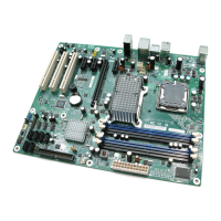
1. Desktop Board D975XBX Components ........................................................................11
2. LAN Connector LEDs....................................................................................................16
3. Location of Standby Power Indicator.............................................................................20
4. Installing the I/O Shield.................................................................................................25
5. Location of Mounting Screw Holes................................................................................26
6. Lift Socket Lever...........................................................................................................27
7. Lift the Load Plate.........................................................................................................27
8. Remove the Protective Socket Cover ...........................................................................28
9. Remove the Processor from the Protective Processor Cover........................................28
10. Install the Processor .....................................................................................................29
11. Close the Load Plate ....................................................................................................29
12. Connecting the Processor Fan Heat Sink Cable to the Processor Fan Header.............30
13. Dual Channel Memory Configuration Example 1...........................................................31
14. Dual Channel Memory Configuration Example 2...........................................................31
15. Dual Channel Memory Configuration Example 3...........................................................32
16. Use DDR2 DIMMs ........................................................................................................33
17. Installing a DIMM ..........................................................................................................34
18. Installing PCI Express Graphics Cards .........................................................................36
19. Removing the PCI Express x16 Card............................................................................37
20. Connecting the IDE Cable ............................................................................................38
21. Connecting Serial ATA Cables......................................................................................39
22. Internal Headers ...........................................................................................................40
23. Connecting the Rear Panel USB 2.0 Adapter ...............................................................43
24. Connecting the Front Panel USB/IEEE 1394/Audio Cables ..........................................44
25. Location of Fan Headers...............................................................................................45
26. Connecting 2x10 Power Supply Cables ........................................................................46
27. Connecting 2x12 Power Supply Cables ........................................................................47
28. Location of Other Connectors .......................................................................................48
29. Location of the BIOS Configuration Jumper Block ........................................................49
30. Back Panel Connectors ................................................................................................51
31. Removing the Battery ...................................................................................................55
32. Accessing the BIOS Setup Program .............................................................................57