Product Description
29
The PCI Express interfaces for the Primary and Secondary PCI Express x16 connectors are routed
through the MCH. The PCI Express interface for the PCI Express x16 (electrical x4) connector is
routed through the ICH7-R/ICH7-DH. Therefore, the Primary and Secondary PCI Express x16
connectors provide higher performance than the PCI Express x16 (electrical x4) bus add-in card
connector.
For information about Refer to
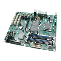
The locations of the specific PCI Express x16 add-in card connectors Figure 1, page 12
#
INTEGRATOR’S NOTE
Although the PCI Express specification allows x16 cards to auto-negotiate down from x16 to x4
and x1 and may function properly, such configurations have not been validated on this board.
Please consult your add-in card vendor prior to attempting to use a PCI Express x16 add-in card in
this connector.
The PCI Express interface supports the PCI Conventional bus configuration mechanism so that the
underlying PCI Express architecture is compatible with PCI Conventional compliant operating
systems. Additional features of the PCI Express interface includes the following:
• Support for the PCI Express enhanced configuration mechanism
• Automatic discovery, link training, and initialization
• Support for Active State Power Management (ASPM)
• SMBus 2.0 support
• Wake# signal supporting wake events from ACPI S1, S3, S4, or S5
• Software compatible with the PCI Power Management Event (PME) mechanism defined in the
PCI Power Management Specification Rev. 1.1
1.8 IEEE-1394a Connectors (Optional)
The optional IEEE-1394 interface addresses interconnection of both computer peripherals and
consumer electronics with these features:
• IEEE-1394a operation
• Support for up to 63 peer-to-peer devices
• Operation ranging from 100 Mbits/sec to 400 Mbits/sec (depending on cable type)
• Connection over short and long distances
• Support for both asynchronous and isochronous data transfer
As a manufacturing option, the board includes two IEEE-1394a connectors as follows:
• One IEEE-1394a connector located on the back panel.
• One IEEE-1394a front-panel connector located on the component side.
For information about Refer to
The location of the back panel IEEE-1394a connector Figure 17, page 56
The location of the front panel IEEE-1394a connector Figure 19, page 58
The signal names of the front panel IEEE-1394a connector Section 2.7.2.6, page 68