Technical Reference
47
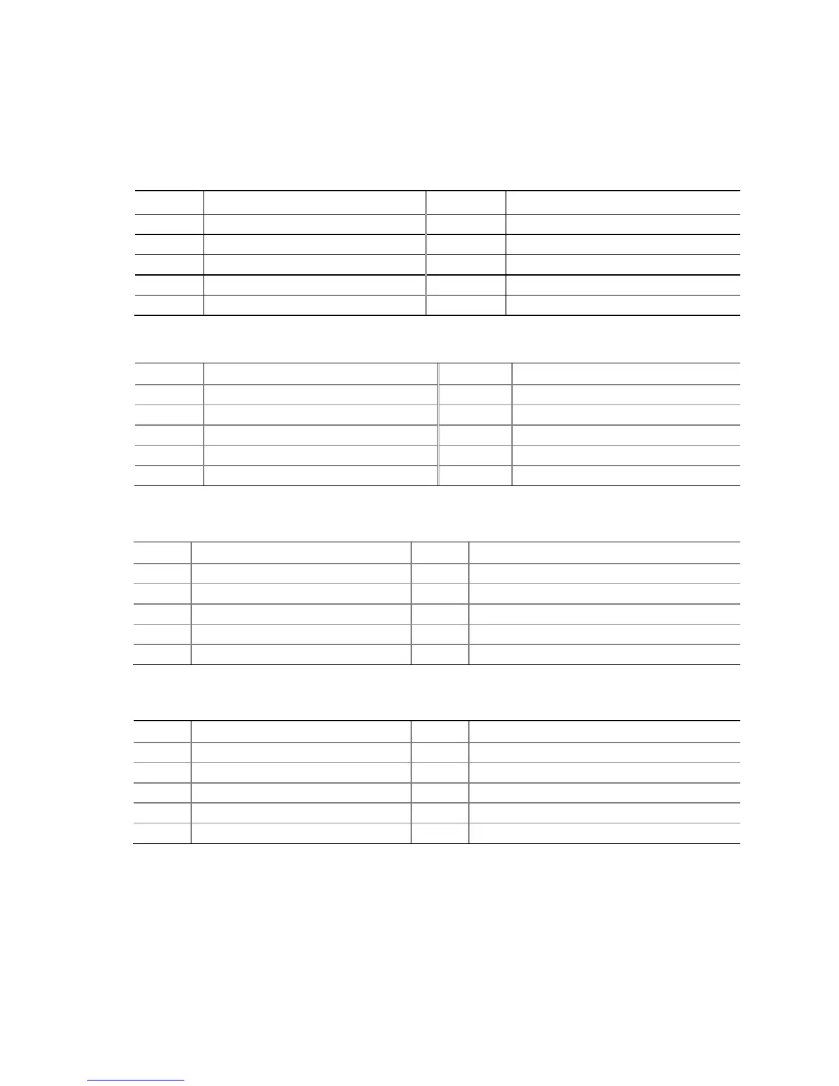
2.2.2.1 Signal Tables for the Connectors and Headers
Table 13. Serial Port Header
Pin Signal Name Pin Signal Name
1 DCD (Data Carrier Detect) 2 RXD# (Receive Data)
3 TXD# (Transmit Data) 4 DTR (Data Terminal Ready)
5 Ground 6 DSR (Data Set Ready)
7 RTS (Request To Send) 8 CTS (Clear To Send)
9 RI (Ring Indicator) 10 Key (no pin)
Table 14. Front Panel Audio Header for Intel HD Audio
Pin Signal Name Pin Signal Name
1 [Port 1] Left channel 2 Ground
3 [Port 1] Right channel 4 PRESENCE# (Dongle present)
5 [Port 2] Right channel 6 [Port 1] SENSE_RETURN
7 SENSE_SEND (Jack detection) 8 Key (no pin)
9 [Port 2] Left channel 10 [Port 2] SENSE_RETURN
Table 15. Front Panel Audio Header for AC ’97 Audio
Pin Signal Name Pin Signal Name
1 MIC 2 AUD_GND
3 MIC_BIAS 4 AUD_GND
5 FP_OUT_R 6 FP_RETURN_R
7 AUD_5V 8 KEY (no pin)
9 FP_OUT_L 10 FP_RETURN_L
Table 16. Front Panel USB 2.0 Headers
Pin Signal Name Pin Signal Name
1 +5 V DC 2 +5 V DC
3 D- 4 D-
5 D+ 6 D+
7 Ground 8 Ground
9 KEY (no pin) 10 No Connect