Contents
vii
Product Ecology Statements ................................................................................71
Recycling Considerations .............................................................................71
China RoHS ...............................................................................................74
EMC Regulations ................................................................................................75
FCC Declaration of Conformity......................................................................75
Canadian Department of Communications Compliance Statement......................76
Japan VCCI Statement ................................................................................76
Korea Class B Statement .............................................................................77
Ensure Electromagnetic Compatibility (EMC) Compliance..................................77
Product Certifications..........................................................................................78
Board-Level Certifications ............................................................................78
Chassis- and Component-Level Certifications..................................................79
ENERGY STAR*, e-Standby, and ErP Compliance ....................................................79
Figures
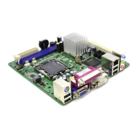
1. Intel Desktop Board DG41TX Components........................................................12
2. LAN Status LEDs ..........................................................................................19
3. Location of the +5 V Standby Power Indicator ..................................................26
4. Installing the I/O Shield ................................................................................31
5. Intel Desktop Board DG41TX Mounting Screw Hole Locations..............................32
6. Lift the Socket Lever .....................................................................................33
7. Lift the Load Plate.........................................................................................34
8. Remove the Protective Socket Cover ...............................................................34
9. Remove the Processor from the Protective Processor Cover ................................35
10. Install the Processor .....................................................................................35
11. Close the Load Plate .....................................................................................36
12. Connecting the Processor Fan Heat Sink Cable..................................................37
13. Dual-Channel Memory Configuration Example...................................................38
14. Use DDR3 DIMMs .........................................................................................39
15. Installing a DIMM .........................................................................................40
16. Installing a PCI Express x16 Card ...................................................................42
17. Removing a PCI Express x16 Card ..................................................................43
18. Connecting the IDE Cable ..............................................................................44
19. Connecting a Serial ATA Cable........................................................................45
20. Connecting the Diskette Drive Cable................................................................46
21. Internal Headers ..........................................................................................47
22. Back Panel Audio Connectors .........................................................................51
23. Location of the Chassis Fan Headers................................................................52
24. Connecting Power Supply Cables ....................................................................53
25. Location of the BIOS Configuration Jumper Block ..............................................54
26. Removing the Battery ...................................................................................61
27. Intel Desktop Board DG41TX China RoHS Material Self Declaration Table..............74