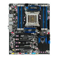
Intel Desktop Board DX79SI Product Guide
20
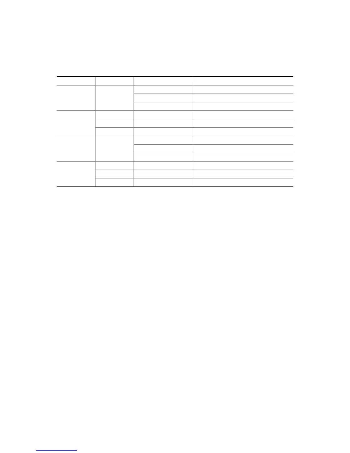
Table 3 describes the LED states when the board is powered up and the LAN
subsystem is operating.
Table 3. LAN Connector LEDs
LED LED Color LED State Indicates
A Green Off LAN link is not established
On LAN link is established
Blinking LAN activity is occurring
B N/A Off 10 Mb/s data rate
Green On 100 Mb/s data rate
Yellow On 1000 Mb/s data rate
C Green Off LAN link is not established
On LAN link is established
Blinking LAN activity is occurring
D N/A Off 10 Mb/s data rate
Green On 100 Mb/s data rate
Yellow On 1000 Mb/s data rate
Legacy I/O
Intel Desktop Board DX79SI includes an I/O controller that provides the following
legacy I/O features:
• Consumer Infrared (CIR) support
• Low pin count (LPC) interface
• Intelligent power management, including a programmable wake up event interface
• PCI power management support
Expandability
Intel Desktop Board DX79SI provides the following expansion capability:
• Three PCI Express 3.0 x16 connectors (two x16 electrical and one x8 electrical).
Operation at PCI Express 3.0 speeds requires a processor that supports the PCI
Express 3.0 Specification.
• Two PCI Express 2.0 x1 connectors
• One PCI bus connector
BIOS
The BIOS provides the Power-On Self-Test (POST), the BIOS Setup program, and the
PCI/PCI Express and IDE auto-configuration utilities. The BIOS is stored in the Serial
Peripheral Interface (SPI) Flash device.
The BIOS can be updated by following the instructions on page 67 in Chapter 3.
 Loading...