Intel Desktop Board DX79SI Product Guide
54
Alternate Front Panel Power LED Header
Figure 22, J shows the location of the alternate front panel power LED header. Pins 1
and 3 of this header duplicate the signals on pins 2 and 4 of the front panel header. If
your chassis has a three-pin power LED cable, connect it to this header.
Table 15 shows the pin assignments and
signal names for the alternate front panel
power LED header.
Table 15. Alternate Front Panel Power LED Header Signal Names
Pin Description In/Out
1 Front panel green LED Out
2 No pin
3 Front panel yellow LED Out
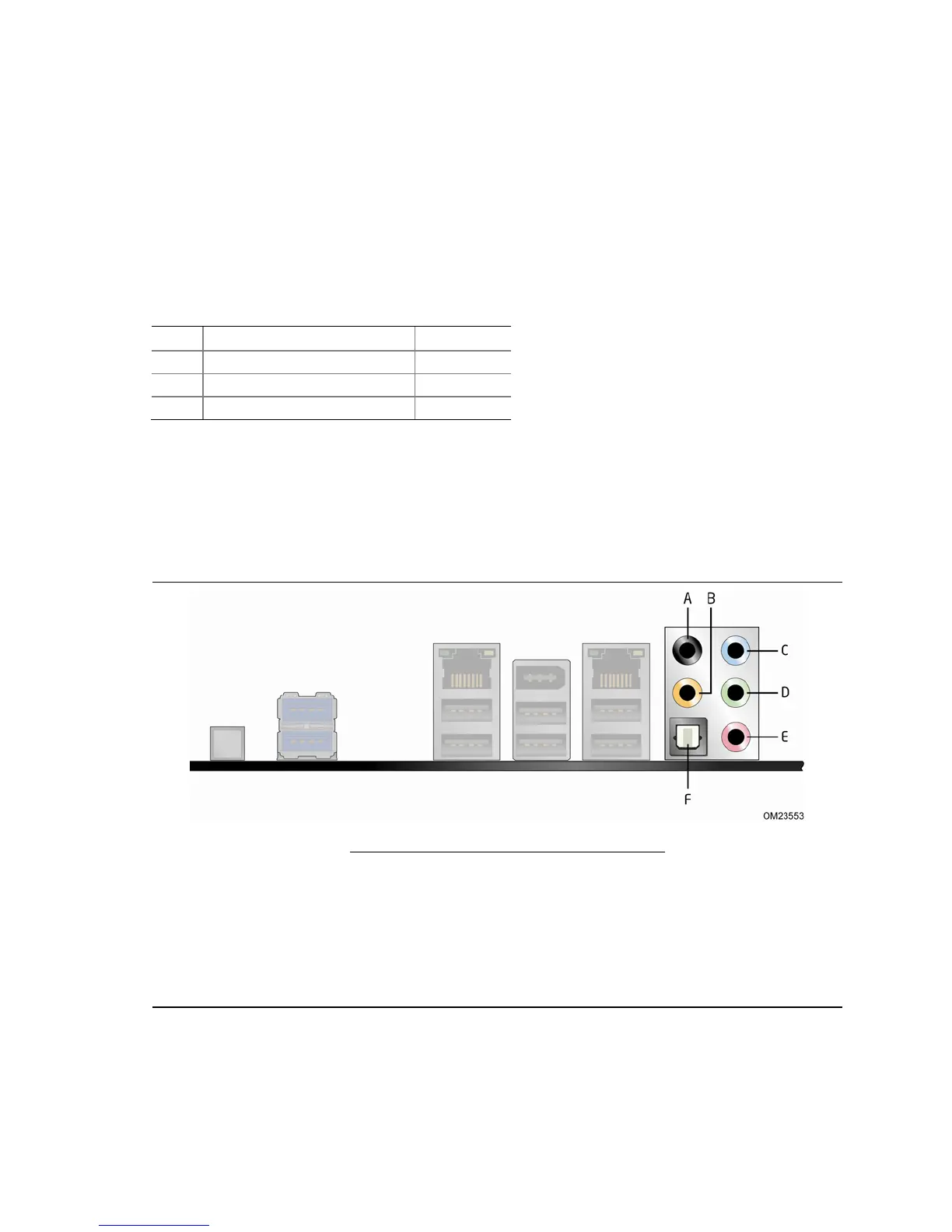
Connecting to the Audio System
After installing the RealTek audio driver from the Intel
®
Express Installer DVD, the
multi-channel audio feature can be enabled. Figure 23 shows the back panel audio
connectors
. The default connector assignments are shown in the table.
Item Description
A Surround Left and Right
B Center Channel and LFE (Subwoofer)
C Side Surround Left and Right/Line
In/Retasking Jack
D Line Out
E Mic In
F S/PDIF Digital Audio Out (Optical)
Figure 23. Back Panel Audio Connectors
 Loading...