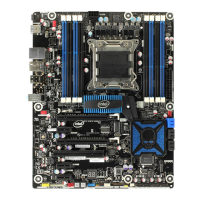
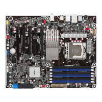
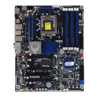
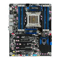
Installing and Replacing Desktop Board Components
51
IEEE 1394a Header
Figure 22, D shows the location of the IEEE 1394a header. Table 9 shows the pin
assignments and signal names for the IEEE 1394a header.
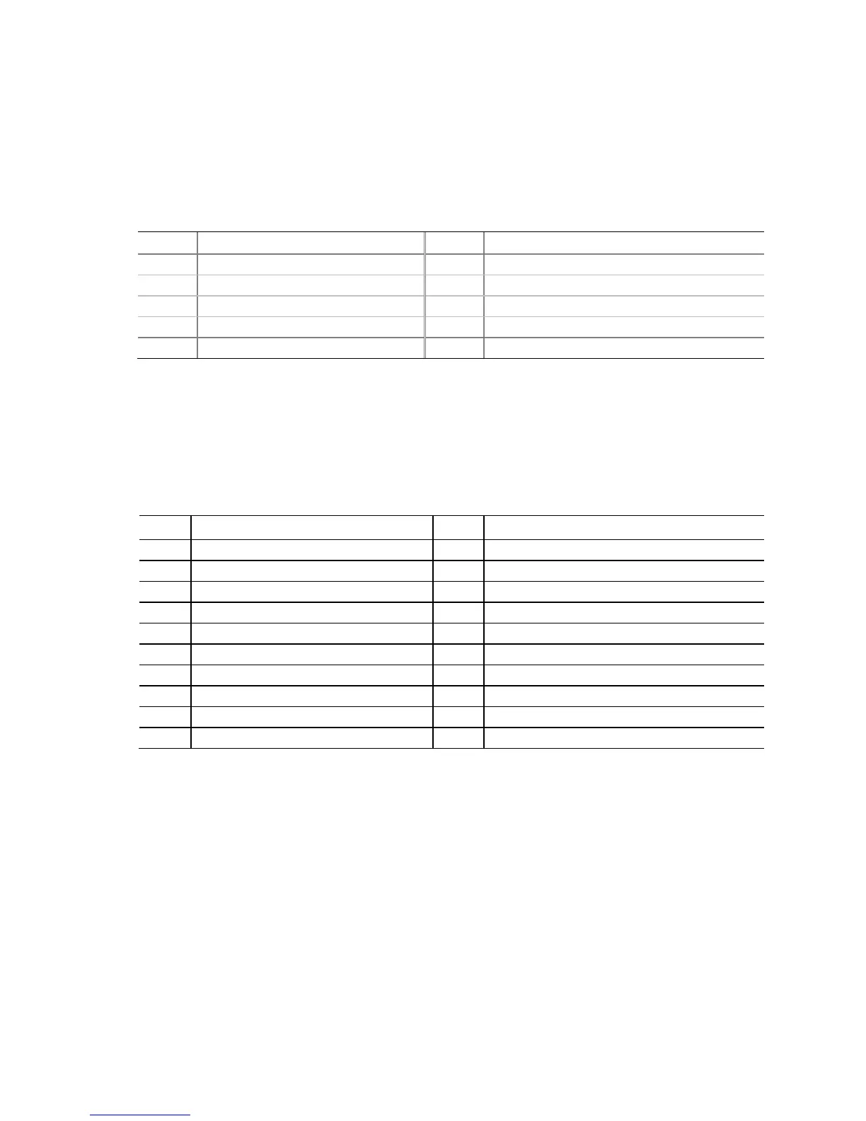
Table 9. IEEE 1394a Header Signal Names
Pin Signal Name Pin Signal Name
1 TPA1+ 2 TPA1-
3 Ground 4 Ground
5 TPA2+ 6 TPA2-
7 +12 V 8 +12 V
9 Key (no pin) 10 Ground
USB 3.0 Connector
Figure 22, E shows the location of the USB 3.0 connector. Table 10 shows the pin
assignments and signal names for the USB 3.0 connector. The USB 3.0 connector can
be used to connect two USB devices.
Table 10. USB 3.0 Connector
Pin Signal Name Pin Signal Name
20 Key (no pin) 1 Vbus
19 Vbus 2 IntA_P1_SSRX−
18 IntA_P2_SSRX− 3 IntA_P1_SSRX+
17 IntA_P2_SSRX+ 4 Ground
16 Ground 5 IntA_P1_SSTX−
15 IntA_P2_SSTX− 6 IntA_P1_SSTX+
14 IntA_P2_SSTX+ 7 Ground
13 Ground 8 IntA_P1_D−
12 IntA_P2_D− 9 IntA_P1_D+
11 IntA_P2_D+ 10 ID
 Loading...