Intel Desktop Board DX79SI Product Guide
50
Front Panel Audio Header
Figure 22, A shows the location of the front panel audio header. Table 6 shows the pin
assignments and signal names for the front panel audio header.
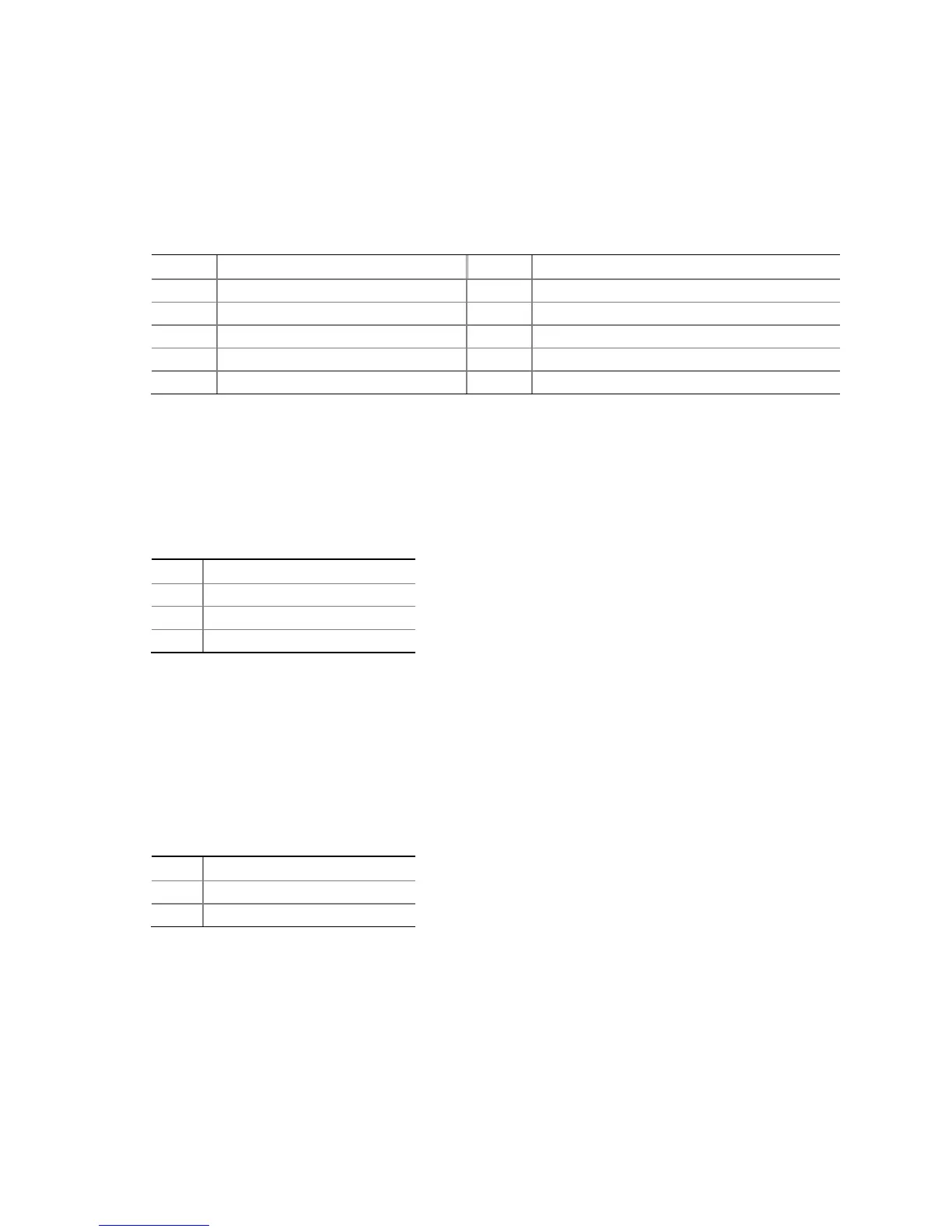
Table 6. Front Panel Audio Header Signal Names
Pin Signal Name Pin Signal Name
1 PORT 1L 2 GND
3 PORT 1R 4 PRESENCE#
5 PORT 2R 6 SENSE1_RETURN
7 SENSE_SEND 8 KEY (no pin)
9 PORT 2L 10 SENSE2_RETURN
S/PDIF Header
Figure 22, B shows the location of the S/PDIF header. Table 7 shows the pin
assignments and signal names for the S/PDIF connector.
Table 7. S/PDIF Header Signal Names
Pin Description
1 Vcc
2 S/PDIF Out
3 Ground
Chassis Intrusion Header
Figure 22, C shows the location of the chassis intrusion header. This header can be
connected to a mechanical switch on the chassis to detect if the chassis cover is
removed.
Table 8 shows the pin assignments and
signal names for the chassis intrusion header.
Table 8. Chassis Intrusion Header Signal Names
Pin Description
1 Intruder
2 Ground
 Loading...