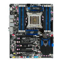
Intel Desktop Board DX79SI Product Guide
viii
19. Removing a PCI Express x16 Card .................................................................. 46
20. Installing Linked PCI Express Graphics Cards .................................................... 47
21. Connecting the Serial ATA Cables .................................................................... 48
22. Internal Headers .......................................................................................... 49
23. Back Panel Audio Connectors ......................................................................... 54
24. Location of the Chassis Fan Headers ................................................................ 55
25. Connecting Power Supply Cables .................................................................... 56
26. Location of the BIOS Configuration Jumper Block .............................................. 57
27. Removing the Battery ................................................................................... 63
28. Installing the WiFi/Bluetooth Module ............................................................... 64
29. Connecting the Remote Thermal Probe ............................................................ 65
30. POST Code LED Display ................................................................................. 75
31. Intel Desktop Board DX79SI China RoHS Material Self Declaration Table .............. 84
Tables
1. Feature Summary .......................................................................................... 9
2. Intel Desktop Board DX79SI Components ........................................................ 13
3. LAN Connector LEDs ..................................................................................... 20
4. System Initialization LEDs .............................................................................. 28
5. Status LEDs ................................................................................................. 29
6. Front Panel Audio Header Signal Names ........................................................... 50
7. S/PDIF Header Signal Names ......................................................................... 50
8. Chassis Intrusion Header Signal Names ........................................................... 50
9. IEEE 1394a Header Signal Names ................................................................... 51
10. USB 3.0 Connector ....................................................................................... 51
11. Front Panel CIR Receiver (Input) Header Signal Names ...................................... 52
12. Back Panel CIR Header Emitter (Output) Header Signal Names ........................... 52
13. USB 2.0 Header Signal Names ........................................................................ 53
14. Front Panel Header Signal Names ................................................................... 53
15. Alternate Front Panel Power LED Header Signal Names ...................................... 54
16. Jumper Settings for the BIOS Setup Program Modes .......................................... 58
17. BIOS Beep Codes ......................................................................................... 73
18. Front-panel Power LED Blink Codes ................................................................. 73
19. BIOS Error Messages .................................................................................... 74
20. Port 80h POST Codes .................................................................................... 76
21. Safety Standards .......................................................................................... 79
22. EMC Regulations ........................................................................................... 85
23. Regulatory Compliance Marks ......................................................................... 88

 Loading...