Do you have a question about the Intelitek SCORA-ER 14 and is the answer not in the manual?
Instructions for safely removing the robot from its packaging and initial handling.
Procedures to check for shipping damage and verify all components are received.
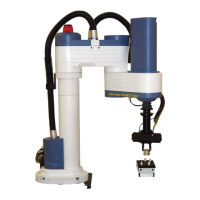
Details the SCORA-ER 14's horizontal articulated (SCARA) mechanical structure and axis movements.
Describes the robot's operational range based on link lengths and joint rotations.
Lists essential safety measures for operating the SCORA-ER 14 robot.
Details critical conditions and actions to avoid when installing or operating the robot.
Steps to prepare the system components before making cable connections.
Guidelines for placing the controller and computer safely relative to the robot.
Instructions for positioning and securing the robot arm on a sturdy surface.
Detailed steps for installing the robot controller unit.
Detailed steps for connecting and installing the robot arm itself.
Procedure to initialize the robot axes to their home positions before operation.
Steps for physically attaching and connecting pneumatic or servo grippers.
How to test and configure the installed gripper for operation.
Overview of software options like ACL, ATS, ACLoff-line, and SCORBASE for robot operation.
Explanation of the hand-held terminal used for robot control, movement, and programming.
Details the components and structure of the drive system for the first two robot axes.
Explains the drive system for axis 3, responsible for Z-axis linear motion.
Describes the drive system for axis 4, responsible for end effector flange rotation.
Discusses the requirements and locations of DC motors used as actuators in the robot.
Details the Harmonic Drive transmission and its four main components.
Summarizes the overall gear ratios for each axis drive.
Explains how electro-optical encoders measure axis location and movement.
Details how encoder resolution is calculated and its impact on joint precision.
Describes limit switches preventing movement beyond functional limits.
Explains mechanical limits that halt motion when software fails.
Discusses optical home switches used to identify the robot's fixed reference position.
Details the power cable, its connector, and pin functions for robot motors.
Explains the encoder cable, its connector, and pin functions for encoders and home switches.
Describes the warning light cable, its connector, and pin functions.
Procedures for daily checks of the robot and controller before and after operation.
Methods for diagnosing and resolving system malfunctions by component exchange.
Lists and explains system messages indicating problems or errors during robot operation.
| Brand | Intelitek |
|---|---|
| Model | SCORA-ER 14 |
| Category | Power Tool |
| Language | English |