4. Set up a guardrail or rope
around the SCORA-ER 14
operating area to protect
both the operator and
bystanders.
SCORA-ER 14 Installation
Controller Installation
Perform the installation procedures detailed in the following sections of Chapter
2, “Installation,” in the ACL
Controller-B
User’s Manual:
•
Computer/Terminal–Controller Installation
•
Power On
•
Controller Configuration
‹
When the Peripheral Setup screen appears at the end of the controller
configuration, select
Gripper Connection: None
. (You will change this setting
after the gripper is installed.) Refer to the section, “Peripheral Devices and
Equipment--Robot Gripper,” in the ACL
Controller-B
User’s Manual.
Robot Installation
‹
Before you begin, make sure the controller POWER switch is turned off.
Refer to Figures 4-3 and 4-4. Refer also to the wiring information and diagram in
Chapter 8.
1. Connect the safety ground wires:
•
Unscrew and remove the nuts and washers from the safety ground studs on
both the robot and controller connector panels.
•
Connect the green/yellow wires from both the robot cable and the encoders
cable to the safety ground studs on both the robot and controller connector
panels.
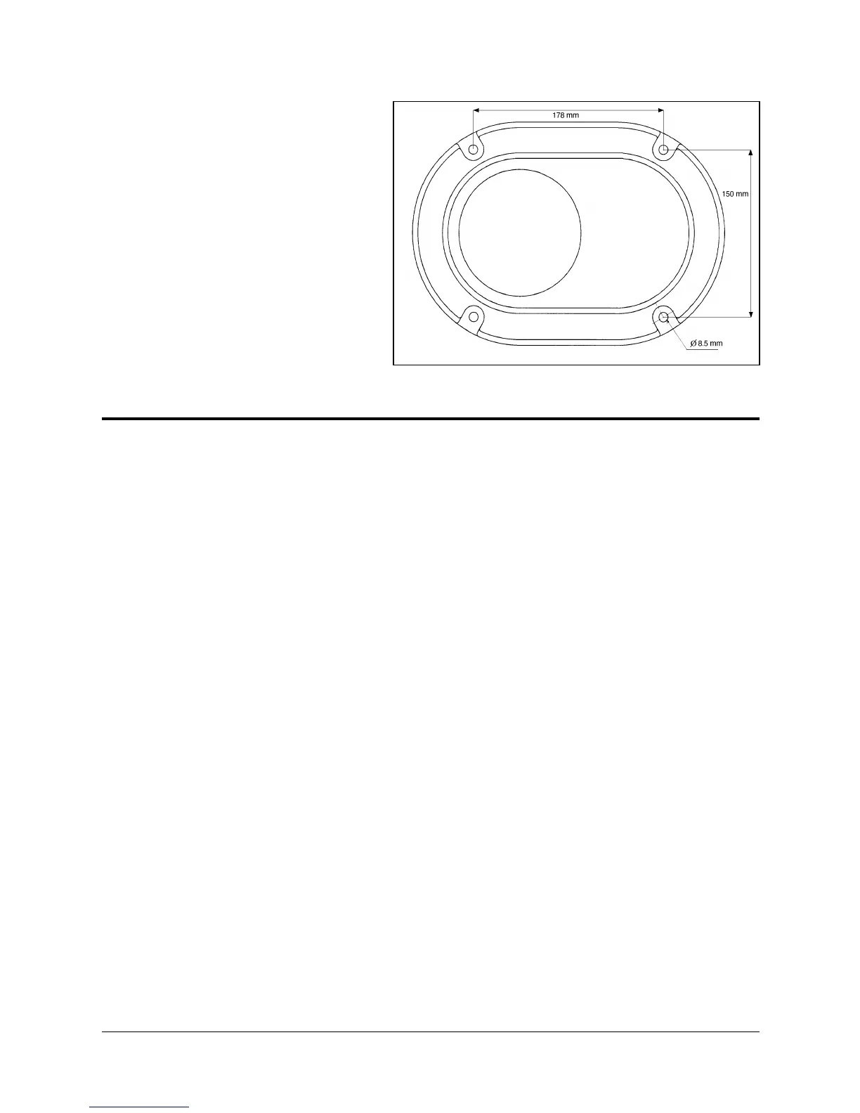
Figure 4-2: Robot Base Layout
SCORA-ER 14 4-2 User’s Manual
9603
 Loading...