Encoder Cable and Connector
Pin
ID
Pin Description
Robot Side (J4)
Axis Wire Type and Color
Pin Description
Controller Side
(J2)
17 A4 (Encoder Pulse A)
4
Twisted
Pair
yellow CHA 3
18 B4 (Encoder Pulse B) black CHB 3
19 C4 (Encoder Index Pulse)
Twisted
Pair
yellow CHC 3
20 COMMON 4 red COMMON 3
34 H4 (Home)
Twisted
Pair
black MSWITCH3
with J2 – 33
21 A5 (Encoder Pulse A)
5
Twisted
Pair
green CHA 4
22 B5 (Encoder Pulse B) black CHB 4
23 C5 (Encoder Index Pulse)
Twisted
Pair
green CHC 4
24 COMMON 5 red COMMON4
35 H5 (Home)
Twisted
Pair
green MSWITCH4
with free yellow
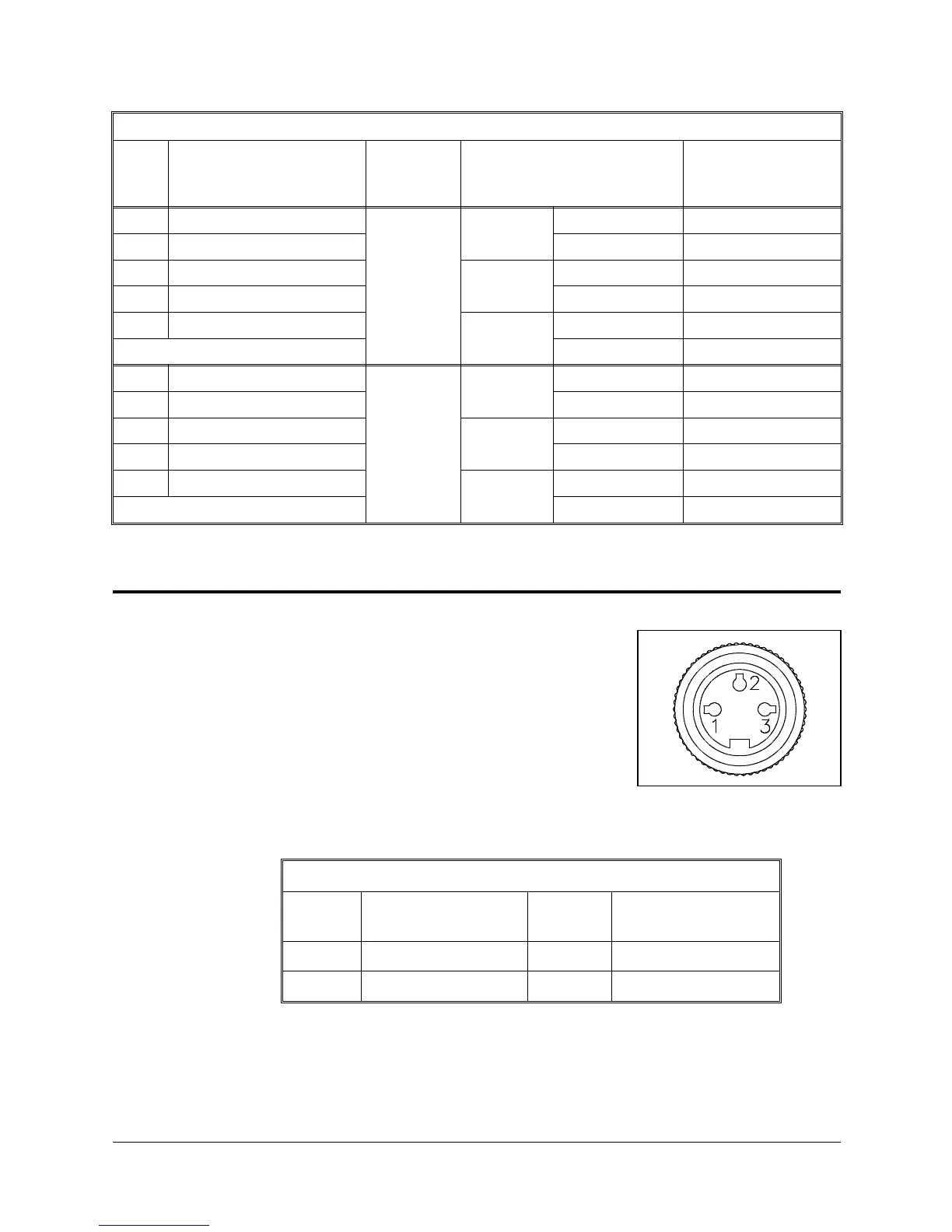
Warning Light Cable and Connector
The warning light cable which connects the
controller to the warning light contains three leads.
Figure 8-4 shows the Amphenol three pin female
connector that joins the warning light cable to the
panel at the base of the robot.
The following table details the warning light cable
and connector.
Warning Light Cable and Connector
Pin
#
Pin Description
Robot Side (J3)
Wire
Color
Pin Description
Controller Side
1NO redNO
2 COM black COM
Figure 8-4. Amphenol 3 Pin
Connector
SCORA-ER 14 8 - 4 User’s Manual
9603
 Loading...