Encoder Cable and Conenctor
The encoder cable, which connects the controller
to the motor encoders and optical home switches,
contains 38 leads in 19 pairs. Only 14 pairs are
used.
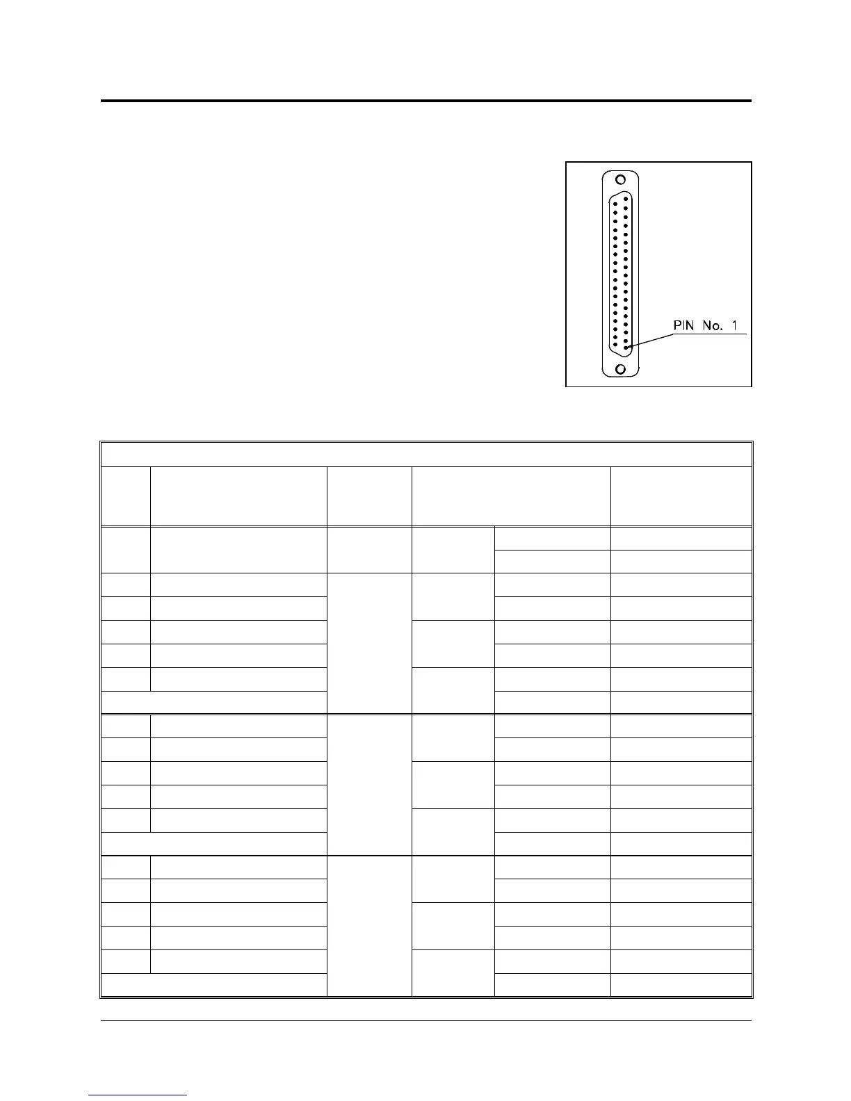
Figure 8-3 shows the D37 female connector that
joins the encoder cable to the connector panel at
the base of the robot.
The following table details the connector pin
functions and the decribes the cable wiring.
Encoder Cable and Connector
Pin
ID
Pin Description
Robot Side (J4)
Axis Wire Type and Color
Pin Description
Controller Side
(J2)
1+5V –
Twisted
Pair
red +5V
2+5V – black +5V
5 A1(Encoder Pulse A)
1
Twisted
Pair
brown CHA 0
6 B1(Encoder Pulse B) black CHB 0
7 C1(Encoder Index Pulse)
Twisted
Pair
brown CHC 0
8 COMMON 1 red COMMON 0
31 H1 (Home)
Twisted
Pair
white MSWITCH 0
with J2 – 32
9 A2 (Encoder Pulse A)
2
Twisted
Pair
red CHA 1
10 B2 (Encoder Pulse B) white CHB 1
11 C2 (Encoder Index Pulse)
Twisted
Pair
red CHC 1
12 COMMON 2 blue COMMON 1
32 H2 (Home)
Twisted
Pair
black MSWITCH 1
with J2 – 31
13 A3 (Encoder Pulse A)
3
Twisted
Pair
orange CHA 2
14 B3 (Encoder Pulse B) black CHB 2
15 C3 (Encoder Index Pulse)
Twisted
Pair
orange CHC 2
16 COMMON 3 red COMMON 2
33 H3 (Home)
Twisted
Pair
blue MSWITCH 2
with J2 – 34
Figure 8-3. D37 Connector
User’s Manual 8 - 3 SCORA-ER 14
9603