CHAPTER
7
Position and Limit Devices
This chapter describes the various elements in the SCORA-ER 14 which play a part
in the positioning of the robot arm and the limiting of its motion.
•
Encoders
•
End of Travel Switches
•
Hard Stops
•
Home Switches
‹
Note that the illustrations of components shown in this chapter are for descriptive
purposes, and may not be the actual components used in the SCORA-ER 14.
Encoders
The location and movement of an axis is commonly measured by an
electro-optical encoder attached to the motor which drives the axis. The encoder
translates the rotary motion of the motor shaft into a digital signal understood by
the controller.
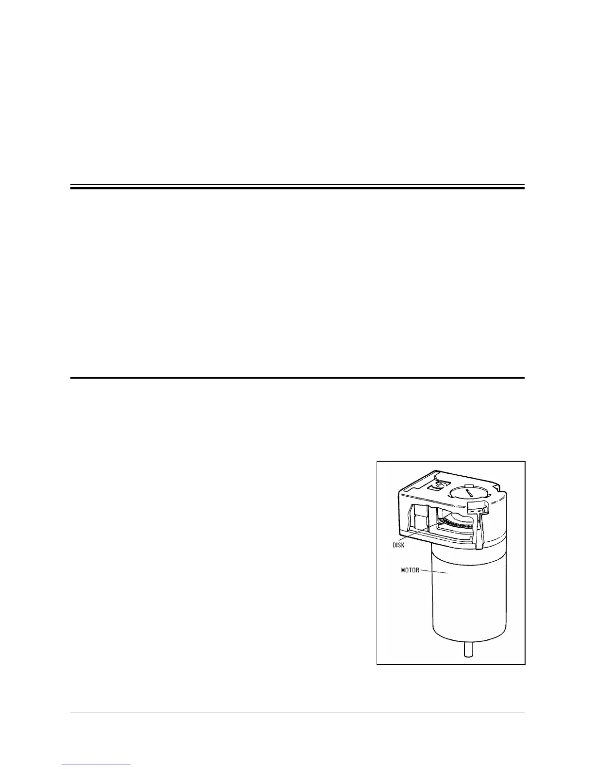
Figure 7-1 shows the encoder mounted on a
SCORA-ER 14 motor.
The encoder used on the SCORA-ER 14 contains
a single light emitting diode (LED) as its light
source. Opposite the LED is a light detector
integrated circuit. This IC contains several sets
of photodetectors and the circuitry for producing
a digital signal. A perforated, rotating disk is
located between the emitter and detector IC.
Figure 7-1:
SCORA-ER 14 Encoder
User’s Manual 7 - 1 SCORA-ER 14
9603
 Loading...