Power (Robot) Cable and Connector
The power (robot) cable, which connects
the controller to the robot motors, contains
12 leads in 6 pairs.
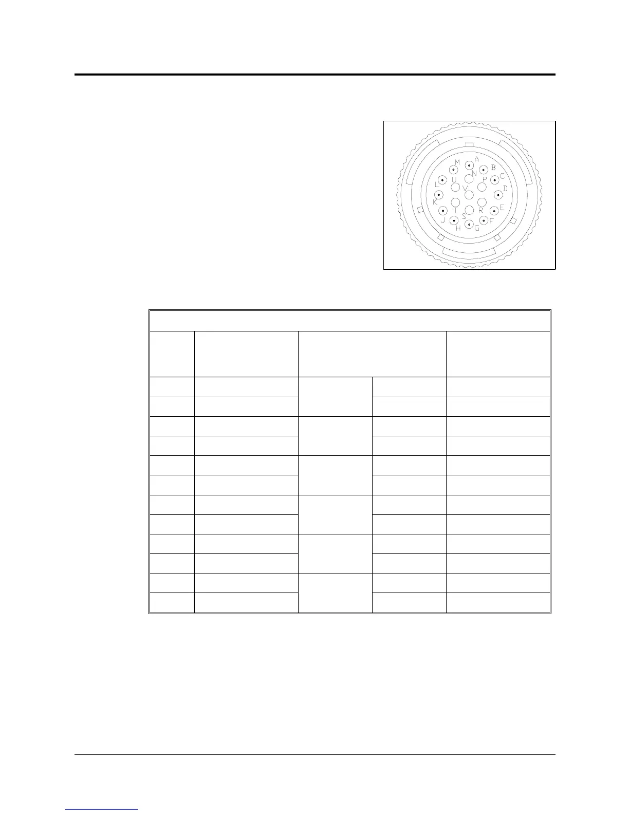
Figure 8-2 shows the Burndy 19 pin female
connector that joins the power cable to the
connector panel at the base of the robot.
The following table describes the connector
pin functions and the cable wiring.
Robot (Power) Cable and Connector
Pin
ID
Pin Description
Robot Side (J1)
Wire Type and Color
Pin Description
Controller Side
(P1)
A Motor 1 –
Twisted
Pair
black M0_A
M Motor 1 + brown M0_B
C Motor 2 –
Twisted
Pair
black M1_A
L Motor 2 + red M1_B
E Motor 3 –
Twisted
Pair
black M2_A
H Motor 3 + blue M2_B
B Motor 4 –
Twisted
Pair
black M3_A
K Motor 4 + yellow M3_B
D Motor 5 –
Twisted
Pair
black M4_A
J Motor 5 + green M4_B
R+24V to PCB
Twisted
Pair
white +24V
S 24VRET to PCB black 24VRET
Figure 8-2. Burndy 19 Pin Connector
SCORA-ER 14 8 - 2 User’s Manual
9603