Remote Switch Input
Ignition/Enable
Remote Switch Input
Ignition/Enable
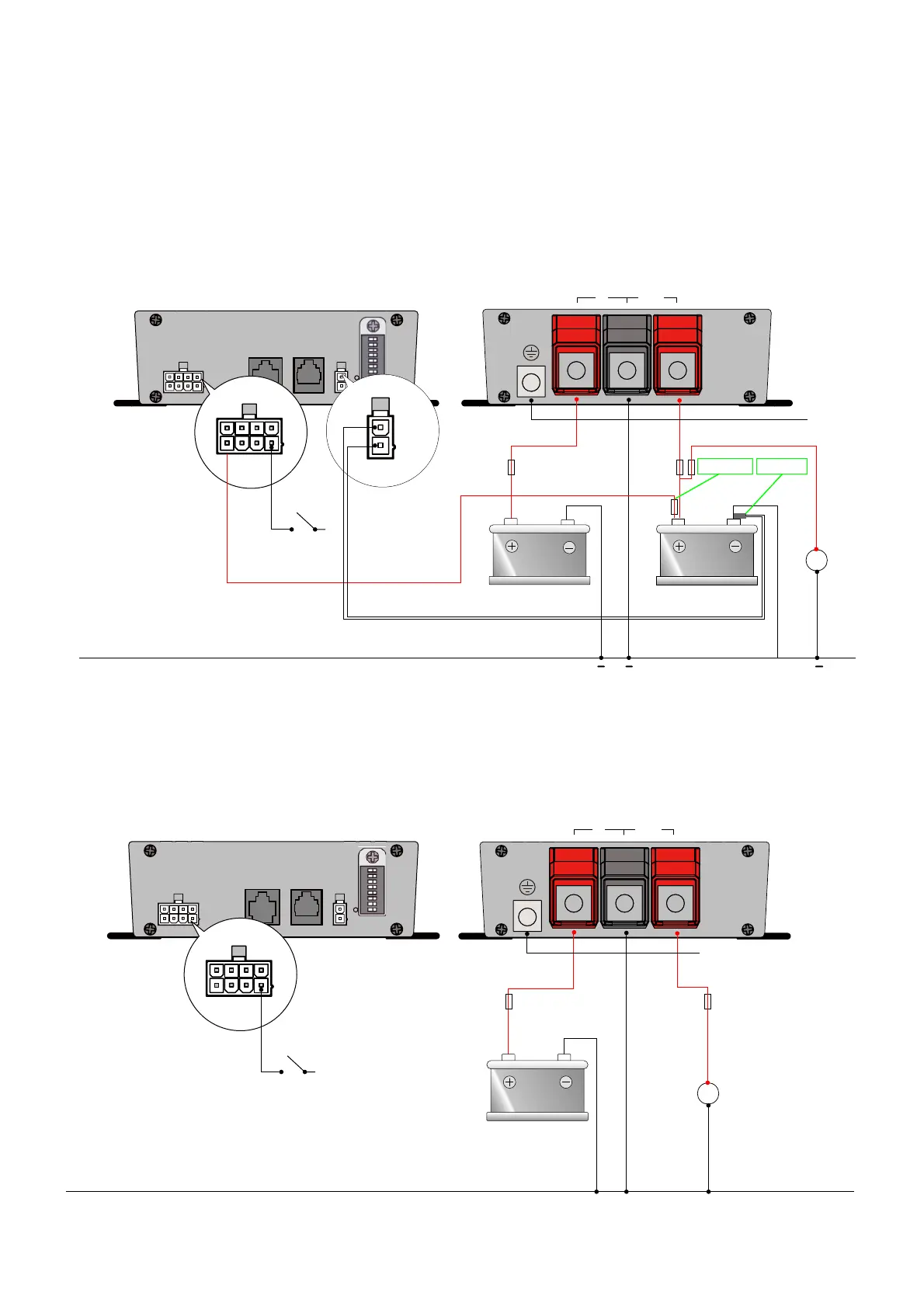
6. Connection
• BBINT50A as a battery charger, see installation drawing A.
• BBINT50A as a stabilised DC power supply, see installation drawing B.
• Use properly sized fuses and wiring.
Installation Drawing A
Installation Drawing B
CN1 LIN
REMOTE
RS-232 TEMP.
0 1
S1
S2
S3
S4
S6
S7
S8
S5
LOAD
Battery Charger
Battery 1
(input)
5
1
2
1
0 1
5
1
Battery 2
(Output)
Battery Voltage
Sensor
IN OUT
PE
PE
LOAD
Stabilized
DC power supply
Battery
(input)
CN1 LIN
REMOTE
RS-232 TEMP.
0 1
S1
S2
S3
S4
S6
S7
S8
S5
5
1
IN OUT
PE
12
Battery Temp
Sensor
Ensure sufficient sized cable is used to common both Input Battery
and Output Battery Negatives together
 Loading...