Mode
Charging Control
S6 S5
0 0
0 1
1 0
1 1
Charger mode 1
Charger mode 2
POWER mode 1
POWER mode 2
bulk→absorpon→float→recharge
bulk→absorpon→OFF→rechage (LiFePO4)
Constant Voltage by DIP S2
Constant Voltage by DIP S3
14
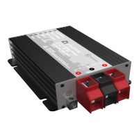
7-2 Dip Switches
The BBINT50 settings can be adjusted in two ways:
• By DIP switches (Basic parameters);
• Via RS-232/Intellitec MV GUI software (Basic parameters+advanced features/custom settings).
This chapter only describes the DIP switch settings
Use a small screwdriver to carefully set the required
settings. You may need to remove the BBINT cables
(or Terminator) to be able to access the DIP switches.
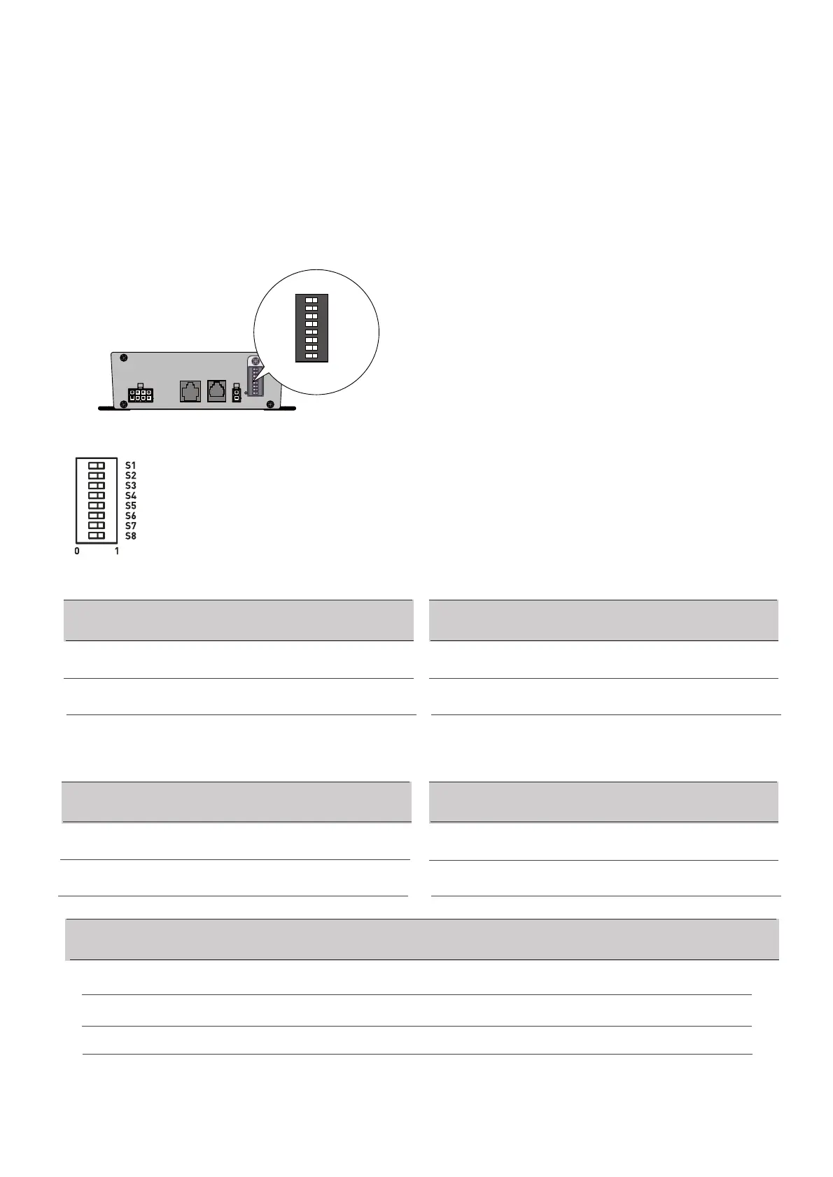
For an overview of the various DIP switch settings,
see the following three tables, where a 0 indicates
OFF or ↓ and a 1 indicates ON or ↑.
CN1 LIN
REMOTE
RS-232 TEMP.
0 1
S1
S2
S3
S4
S6
S7
S8
S5
0 1
S1
S2
S3
S4
S6
S7
S8
S5
Ensure DIP SW 8 is in position‘1' when using DIP switch settings.
Absorpon Voltage
0
S1
1
14.4V
14.7V
Float Voltage
0
S2
1
13.5V
13.8V
Recharge Voltage
0
S3
1
12V
12.8V
Charge Current
0
S4
1
100%
De-rang 50%
 Loading...