MIXING CONSOLE
23
IMX-824/832/840
Cable and Connector Configurations
Cable and Connector Configurations
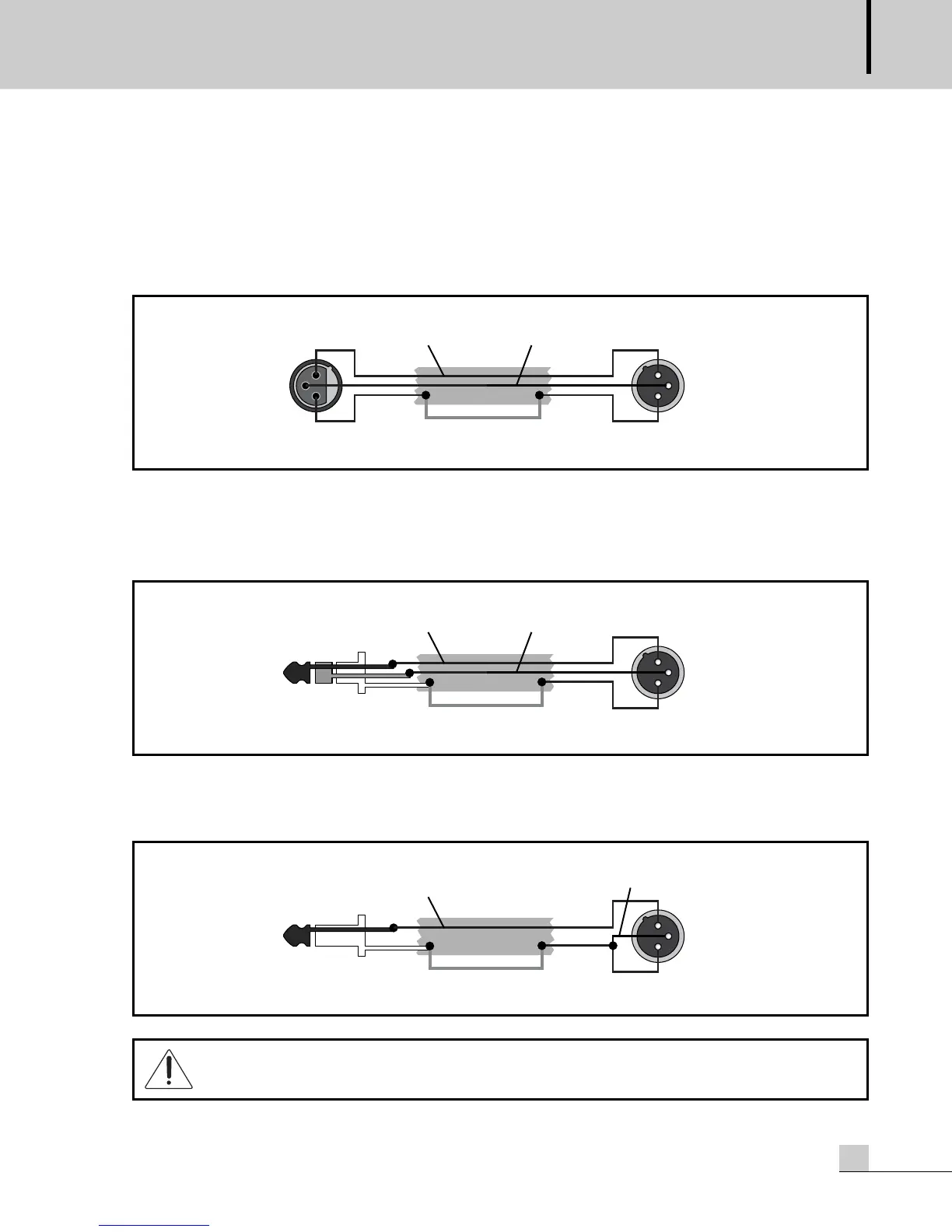
The mic input accepts XLR-type connectors and is designed to accommodate a wide range of balanced low-level
signals, whether from delicate vocals requiring the best low-noise performance or close-miked drum kits needing
maximum headroom.
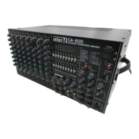
Balanced signals coming from outboard equipment also may be used with this XLR-type connector. Please make
sure that HIGH signal (Tip = T) is connected to pin-2, LOW signal (Ring = R) is pin-3 and ground (Sleeve = S) is
pin-1. The correct configuration of these connections will give you proper signal polarity and will minimize hum
and noise.
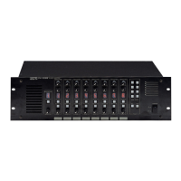
An unbalanced source only has “high” (hot) and ground. Any balanced input to the Mixer always uses pin 2
and pin 3 (XLR) or tip and ring (TRS) for signal connections. When you want to use unbalanced equipment with
the mixer, connect Sleeve (= ground) to both pin-3 and pin-1.
DO NOT use unbalanced sources with the phantom power switched on. The voltage on pins 2 & 3
of the XLR connector may cause serious damage.