CAUTION
A fused spur or an unswitched socket must be located no
more than 1 metre from the appliance.
For installation in damp rooms a fixed connection is
obligatory.
When working on the electrical circuit always isolate the
electric supply.
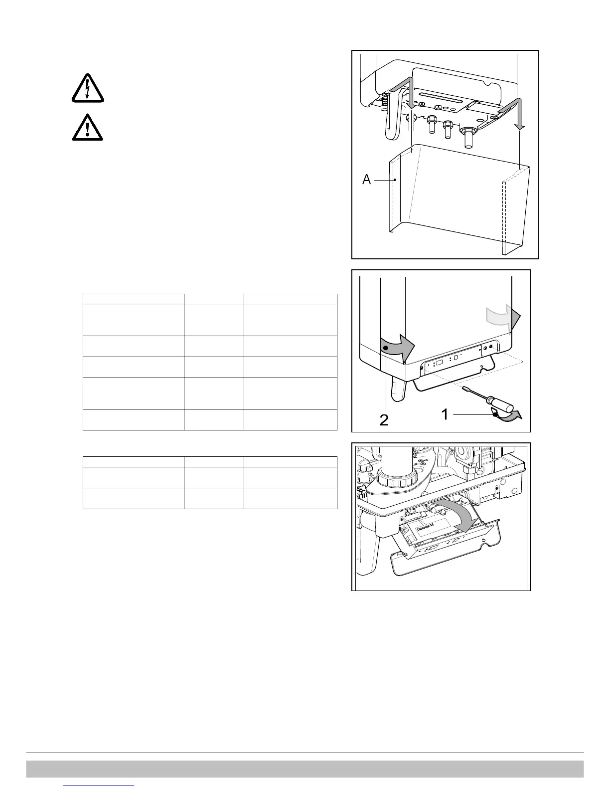
1. Slide the cover plate (A) (if present) to the front to remove.
2. Open the display cover and unscrew both screws to remove the front cover.
3. Pull the boiler controller unit forwards; the boiler controller will tip downwards to
provide access.
4. Consult sections § 8.3.1 and chapter 13 for making the connections.
5. After making the desired connections plug the appliance into an earthed wall
socket.
8.3.1 Electrical connections
Temperature control Connector X4 Notes
Room thermostat 6 – 7 Voltage free room
thermostat.
Remove link 6-7
Outside temperature
sensor
8 – 9 -
Frost protection
thermostat
6 – 7 Parallel to room
thermostat
Power supply 24 V DC 6 – 7 – 9 6 = 24 V DC
7 = room thermostat
9 = 0 V DC
Open Therm (OT) 11 – 12 Remove link 6-7
Temperature control Connector X2 Notes
Room thermostat 230 V or
external control 230 V
1 – 3 Remove link 6 – 7
(connector X4)
Frost thermostat 230 V 1 – 3 Remove link 6 – 7
(connector X4)