Intergas Heating Ltd
47
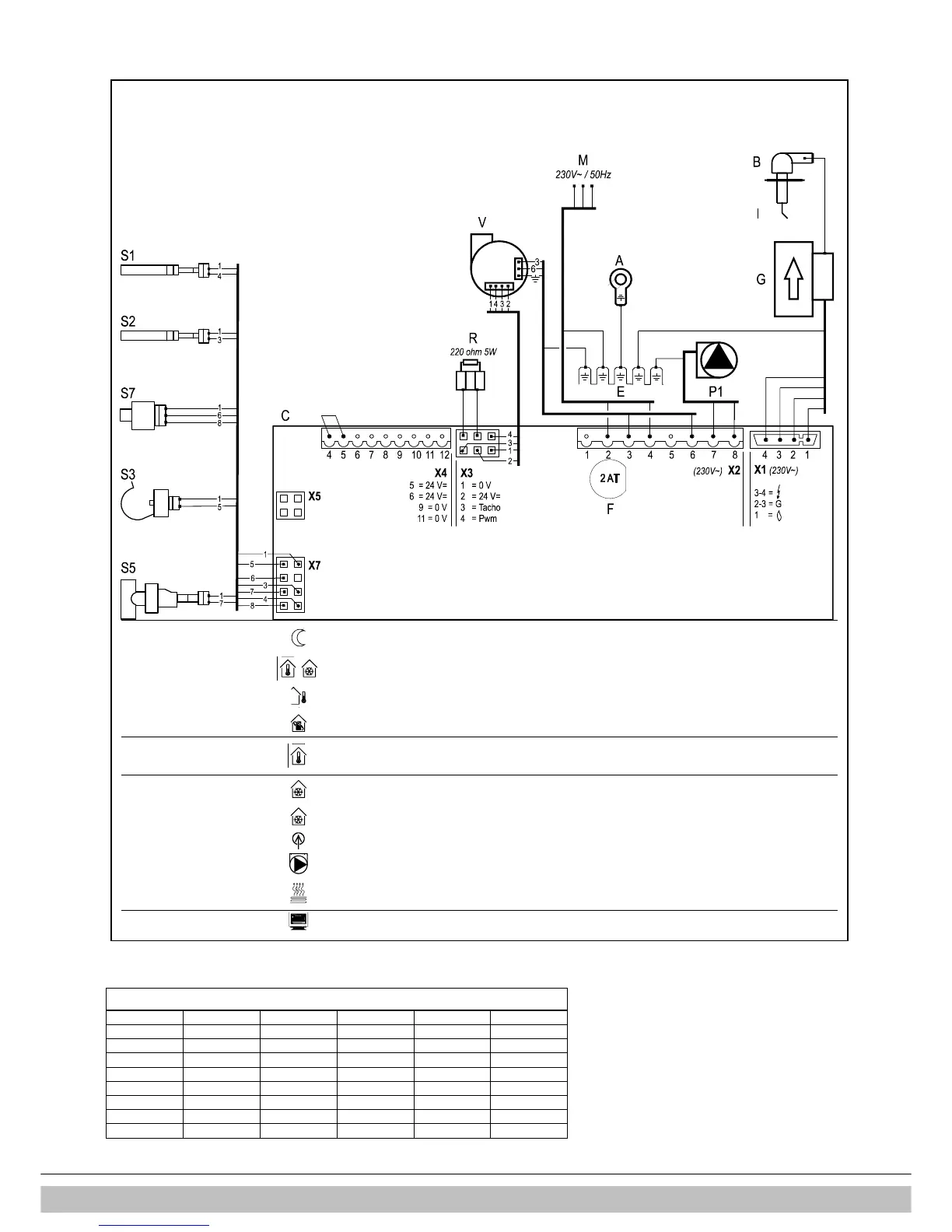
13.2 Electrical diagram HRE 36/40
A
Earth connections heat-exchanger
F
Fuse (2A T)
P1
CH pump
S3
DHW sensor
B
Spark plug cover
G
Gas valve + ignition unit
R
Resistance
S5
Flow switch
C
Boiler controller
I
Ionisation-/ ignition probe
S1
Flow sensor
S7
CH water pressure sensor
E
Earth connections boiler controller
M
Main voltage
S2
Return sensor
V
Fan
Connector X4
24V=
4-5
External saving switch
(remove connection)
6-7
On/off room thermostat
(0,1A-24Vdc)
and/or frost thermostat
(remove connection 6-7)
8-9
External sensor
(12k ohm / 25°C)
11-12
OpenTherm thermostat
(remove connection 6-7)
Connector X2
230V
~
1-3
Room thermostat 230 AC
(1 = Switch live, 3 = Live(fused)
1-3
Frost thermostat 230 AC
(1 = Switch live, 3 = Live(fused)
3-6
Power supply (230 V) fan
2-4
Mains
(2 = Live (brown), 4 = Neutral (blue))
7-8
CV-pump
(8 = Live (brown), 7 = Neutral (blue)
3-5-6
Shut-off valve, floor heating
(3 = Live (brown), 5 = Switch (black), 6 = Neutral (blue) (VC4013 Honeywell
230V~)
Connector X5
13.3 NTC resistances
NTC 12kOhm