Intergas Heating Ltd
41
11 FAULTS
11.1 Fault codes
If the fault LED is flashing, the boiler controller has detected a fault. A fault code will be
indicated on the main display.
Once the fault has been rectified the boiler controller can be restarted.
Press the reset key on the operating panel.
The following faults are distinguished
Main display
Display Fault Possible Solution
10, 11, 12,
13, 14
Sensor fault S1
Flow switch does not disconnect
•
Check wiring for break
•
Replace S1
•
Check flow switch
20, 21, 22,
23, 24
Sensor fault S2
•
Check wiring for break
•
Replace S2
0 Sensor fault after self check
•
Replace S1 and/or S2
1 Temperature too high
•
Air in installation
•
Pump not running
•
Unsufficient flow in installation, radiators closed, pump setting too low
•
Flow switch sticking
2 S1 and S2 interchanged
•
Check cable loom
•
Replace S1 or S2
4 No flame signal
•
Gas tap closed
•
No or incorrect ignition gap
•
Gas supply pressure too low of failling
•
Gas valve or ignition unit not powered
5 Poor flame signal
•
Condensate drain blocked
•
Check adjustment of gas valve
6 Flame detection fault
•
Replace ignition cable + spark plug cap
•
Replace ignition unit
•
Replace boiler controller
8 Incorrect fan speed
•
Fan catching on casing
•
Wiring between fan and casing
•
Check wiring for poor wire contact
•
Replace fan*
29,30 Gas valve relay faulty
•
Replace boiler controller
CAUTION
Always use original Intergas spare parts when replacing
components.
Failure to fit the sensors S1 and/or S2, or to fit them correctly can
result in serious damage.
11.2 Other faults
11.2.1 Burner does not ignite
Possible causes: Solution:
Gas tap is closed.
Open gas tap.
No
Air in the gas pipe. Remove air form gas pipe.
No
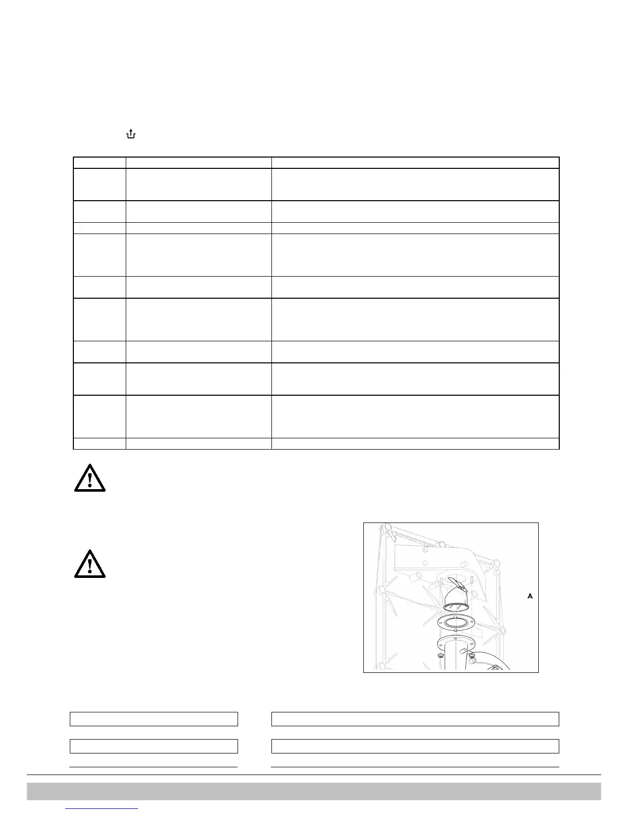
CAUTION
* The boiler is equipped with a non-return valve (A),
positioned above the fan. Ensure the non-return valve is
repositioned correctly when replacing the fan.