EasyManuals Logo

Intermec EasyCoder PX4i Service Manual

Intermec EasyCoder PX4i
282 pages
To Next Page IconTo Next Page
To Previous Page IconTo Previous Page
Page #26 background imageLoading...
Page #26 background image
16 EasyCoder PX4i and PX6i Service Manual
Chapter 2 — Front and Keyboard
2.1 Front
The moulded front part is attached to the center section using four #T20
screws and to the bottom plate using two #T20 screws. The front mould-
ing is provided with holes for mounting a cutter connector (4-pin female
DIN-type).
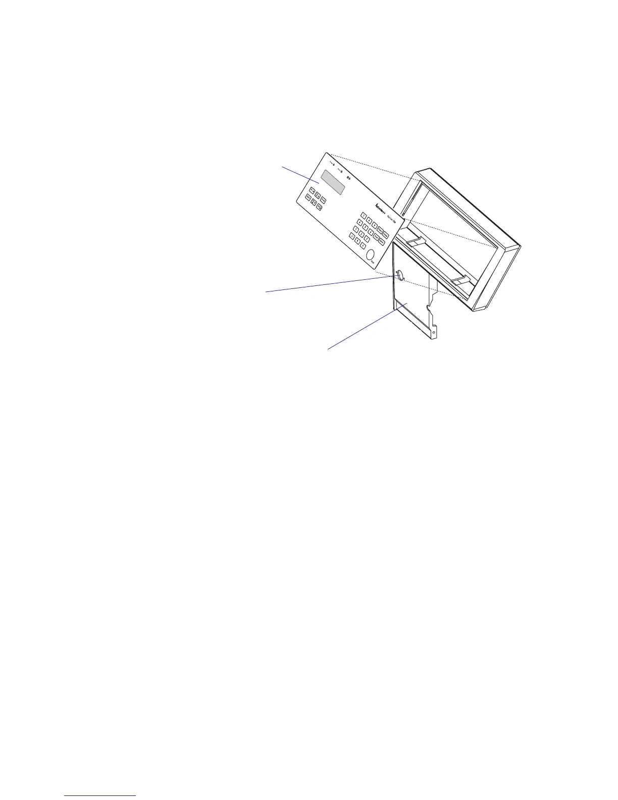
At the top part of the front moulding, there is a cavity for the keyboard/
display assy. This assembly is affi xed using two 2 mm hexagon grub screws
underneath the keyboard part of the front moulding.
Keyboard/display assy.
Provision for cutter
connection
Front moulding

Table of Contents

Other manuals for Intermec EasyCoder PX4i

Questions and Answers:

Question and Answer IconNeed help?

Do you have a question about the Intermec EasyCoder PX4i and is the answer not in the manual?

Intermec EasyCoder PX4i Specifications

General IconGeneral
Print technologyDirect thermal
Maximum resolution300 x 300 DPI
DisplayLCD
Product colorSilver
Keyboard layoutNumeric
Standard interfacesRS-232, USB 2.0
Internal memory16 MB
Media thickness2.4/10 mm
Maximum label width120 mm
Maximum label length2.7 m
Maximum roll diameter213 mm
Supported network protocolsTCP/IP, LPR/LPD, FTP, BOOTP, DHCP, HTTP, SNMPv3, SMTP, SNMP-MIB II
Power requirements90 - 265 VAC, 45 - 65Hz
Power consumption (standby)20 W
Power consumption (printing)125 W
Storage temperature (T-T)-20 - 70 °C
Operating temperature (T-T)40 - 104 °F
Operating relative humidity (H-H)10 - 90 %
Weight and Dimensions IconWeight and Dimensions
Depth482 mm
Width238 mm
Height275 mm
Weight12850 g

Related product manuals