Section 1: Overview
1.2 Front Panel Connectors and Controls
GPS RADIO
RTK Bridge
MODEM
MDM
TXD
SVR SIG GPS PWR
3
1
2
4
CONFIG DATA
1 2
987
54
3
6
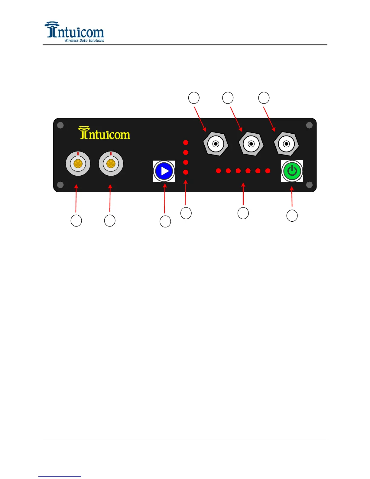
Figure 1-1: RTK Bridge - Cellular Front Panel
(1) Configuration / Power Port
(2) Data Copy Output / External GPS Input / Power Port
(3) Profile Select / Mode Select Button
(4) Current Profile / Modem Signal Strength (Antenna Aiming Mode)
(5) Status LEDs
(6) Power On/Off Button
(7) TNC antenna connector for internal CDMA/GSM/GPRS/EDGE modem
(8) TNC antenna connector for internal L1 GPS
(9) TNC antenna connector for internal Intuicom 900 MHz Wireless Data Radio or other
embedded data radio
Revision 1.4 2 © 2009 Intuicom, Inc.