EasyManua.ls Logo

Intuicom RTK Bridge - User Manual

Intuicom RTK Bridge
47 pages
Print Icon
To Next Page IconTo Next Page
Loading...
Intuicom, Inc.
1880 S Flatiron Court
Boulder, CO 80301
(303) 449-4330
www.intuicom.com
Intuicom
®
Wireless RTK Bridge - Cellular
User Guide

Questions and Answers

  • M
    Martha SpenceAug 16, 2025
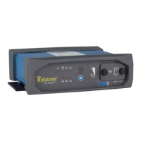
    Why does the MDM LED never light on my Intuicom RTK Bridge?
    • K
      Kylie HartAug 16, 2025
      If the MDM LED on your Intuicom Network Hardware never lights up, first, ensure you're within the carrier's coverage area. Then, check that a good cellular antenna is properly attached and oriented. For CDMA units, verify successful activation. For GSM units, confirm activation, a correctly inserted active SIM, and properly configured APN parameters. Also, double-check the carrier log-in parameters, such as username and password.
  • L
    Lisa DudleyAug 19, 2025
    What to do if the SIG LED never lights on Intuicom RTK Bridge?
    • M
      Matthew MurraySep 12, 2025
      If the SIG LED on your Intuicom Network Hardware unit never lights up or blinks, it could be due to several reasons. First, confirm that you are operating within the cellular carrier's coverage area. Second, ensure that a cellular antenna is connected; in areas with weak coverage, a directional antenna might be necessary. Finally, if the signal is weak or intermittent, try moving to an area with better coverage or improving the antenna.
  • K
    Kaitlyn MillerAug 22, 2025
    How to fix GPS LED if it never lights on Intuicom RTK Bridge Network Hardware?
    • C
      Christian ReeseAug 22, 2025
      If the GPS LED on your Intuicom Network Hardware never lights up, first, check that the unit's POSITIONING mode is configured for REALTIME or DATA PORT, not STATIC GPS. Then, confirm that a good GPS antenna is attached to the GPS TNC antenna port on the front panel and is oriented outdoors with good sky visibility. If using an external device on the DATA port for GPS (GGA) messages, ensure the device is sending messages and its GPS is tracking, and verify the baud rate on the data port.
  • R
    Ryan JohnsonAug 25, 2025
    What to do if SVR LED is on, but no TXT LED and reboots on Intuicom RTK Bridge Network Hardware?
    • T
      Timothy ShannonAug 25, 2025
      If your Intuicom Network Hardware unit's SVR LED is on, but the TXT LED isn't and then it reboots, the mountpoint configuration might be incorrect. To resolve this, select a valid NTRIP mountpoint.
  • A
    Ashley PhillipsAug 27, 2025
    Why is TXT LED blinking but no RTK correction messages on Intuicom RTK Bridge?
    • L
      lburnsAug 27, 2025
      If the TXT LED is blinking correctly on your Intuicom Network Hardware, but the GNSS Rover isn't receiving RTK correction messages, confirm that the baud rate between the RTK Bridge and GNSS Rover matches. Also, ensure that the GNSS RTK message type from the GNSS Server matches the message type configured for the Rover GNSS unit. Change the message type on the Rover GNSS unit and/or the mountpoint from the GNSS Server to match.
  • D
    deborah79Aug 30, 2025
    Why SVR LED is on but no TXT LED and no correction messages on Intuicom RTK Bridge Network Hardware?
    • J
      Jessica ReedAug 30, 2025
      If the SVR LED on your Intuicom Network Hardware is on, but the TXT LED isn't, and the unit can connect to the TCP port and configured mountpoint, but no correction messages are streamed, there are a couple of potential causes. First, ensure that the sending of GPS messages to the server is turned on, as a valid GPS stream is required to obtain corrections. Second, confirm that the correction server is operational and capable of outputting corrections on the selected port/Mountpoint.
  • R
    Richard JohnstonSep 2, 2025
    Why does the SVR LED blink slowly on Intuicom Network Hardware?
    • J
      Jesse HobbsSep 2, 2025
      If the SVR LED on your Intuicom Network Hardware blinks on and off slowly, and the unit reboots, it may be due to an incorrect username or password. Obtain the correct username and password for your account on the GNSS server. Alternatively, the username may already be in use on the GNSS server, which is configured to not allow multiple simultaneous logins. In this case, obtain another username/password or request the GNSS server administrator to allow multiple simultaneous logins for your username/password.
  • A
    alexisbruceSep 5, 2025
    How to establish link for Remote RTK Rover units via wireless embedded radio on Intuicom RTK Bridge Network Hardware?
    • B
      brennanamandaSep 5, 2025
      If the Remote RTK Rover units are unable to establish a link via wireless embedded radio on your Intuicom Network Hardware, confirm that both the RTK Bridge and Rovers have matching channel configurations and the same channel selected. Additionally, ensure that there's a good antenna and transmission line.
  • N
    Nathan GuerreroSep 7, 2025
    What to do if Remote RTK Rover units link but don't receive correction messages on Intuicom RTK Bridge?
    • S
      smithloriSep 7, 2025
      If the Remote RTK Rover units link, but do not receive correction messages on your Intuicom Network Hardware, check the correction message type and rover configuration. The correction type on the rover may need to be changed, or the RTK Bridge may need to connect to a different NTRIP mountpoint or socket. Ensure the rover is configured to receive the correction message type being broadcast.
  • B
    briansalazarSep 10, 2025
    How to troubleshoot no power LED indicator on Intuicom RTK Bridge Network Hardware?
    • M
      Michael BrownSep 10, 2025
      If there is no Power LED indicator on your Intuicom Network Hardware, confirm the power-up operation outside the tractor. Check that the cable wiring is correct, and if the cable assembly is non-operable, replace it.

Summary

1 Overview

1.1 Key Features

Lists the primary capabilities and functionalities of the RTK Bridge.

1.2 Front Panel Connectors and Controls

Details the physical ports, buttons, and LEDs on the RTK Bridge front panel.

1.3 Example Applications

Illustrates typical use cases and scenarios for the RTK Bridge.

1.4 Leveraging Existing Data Radios

Explains how to utilize the RTK Bridge with external third-party radios.

1.5 Extending Cellular Data Reach

Describes extending data service range for rovers using cellular.

2 Initialization and Configuration

2.1 Accessing the Configuration Menu

Explains how to connect a PC to the RTK Bridge to access its configuration interface.

2.2 Embedded Cellular Modem Activation

Details the process of activating the internal cellular modem for network connectivity.

2.3 Verizon Service Setup

Specific steps for establishing and activating Verizon cellular service for the device.

2.4 GSM;GPRS;EDGE Service Setup

Steps for establishing and activating GSM/GPRS/EDGE cellular service.

2.5 APN, Username, and Password Setup

Configuration of APN, username, and password for cellular network access.

2.6 Configuration Process

Outlines the process of setting up the four configurable Profiles for the RTK Bridge.

2.7 Profile and Connection Settings

Details Profile selection, connection modes, server IP, port, and NTRIP mountpoint.

2.8 Positioning and Authentication Settings

Covers GPS positioning reporting and network server authentication setup.

2.9 Internal Radio Configuration

Configuration options for the internal 900MHz spread spectrum data radio.

2.10 Data Port and Network Settings

Settings for Data Port baud rate, Network ID, packet sizes, and repeaters.

2.11 Administrative Options

Access to unit maintenance, firmware upgrades, and advanced wireless settings.

3 Operation

3.1 Basic Steps for Operation

Fundamental steps for physically setting up and preparing the RTK Bridge for operation.

3.2 Startup Sequence

Describes the unit's boot-up process and the meaning of status indicators.

3.3 Front Panel LEDs

Explains the status indicated by the PWR, GPS, SIG, MDM, SVR, TXD, and Profile LEDs.

3.4 Config Port Status Display;Messages

Monitoring current operational status and messages via the Config Port.

3.5 Antenna Aiming; Cellular Signal Strength Mode

Special mode for aiming directional cellular antennas to optimize signal strength.

3.6 Changing Profiles

How to switch between configured operational profiles without using a PC.

3.7 Optimizing Wireless Performance

Tips for improving range and performance of the wireless data radio network.

3.8 Connecting to Third-Party Radio

Steps to connect the RTK Bridge to external third-party radios for data transmission.

4 Troubleshooting

4.1 Common Issues and Solutions

Lists common problems and their corresponding solutions for the RTK Bridge.

5 Accessories

5.1 Available Kits and Accessories

Lists the various kits and accessories available for the RTK Bridge.

6 Technical Support

6.1 Contact Information

Provides contact details for obtaining technical assistance from Intuicom.

7 FCC Notification

7.1 Regulatory Compliance

Information regarding FCC rules and compliance for the device.

8 Warranty

8.1 Limited Warranty Terms

Details the limited warranty coverage and terms for Intuicom products.

Intuicom RTK Bridge Specifications

General IconGeneral
ModelRTK Bridge
Power Supply9-36 VDC
ManufacturerIntuicom
CategoryNetwork Hardware
Frequency900 MHz
Data Link ProtocolSerial
ConnectivityEthernet, Serial