InMode Without Vasculaze Operator Manual
Section 4: Device Description
Figure -1: Two RF Connectors on the Rear Panel (Arrows)
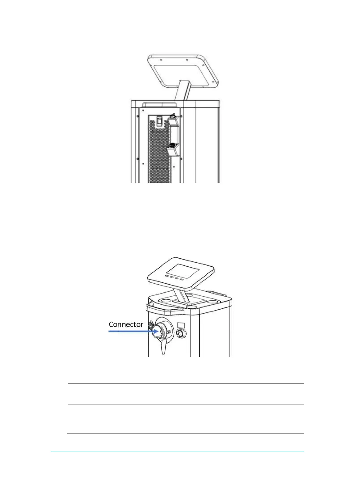
Front Panel and Operator Control Panel
The Operator Control Panel is located on the upper side of the System. The Operator
Control Panel consists of an LCD touch screen with four buttons.
Figure -2: Front Panel and Operator Control Panel with Optical Handpiece Connector
(Arrow)
The Power Switch turns the System on and off. The Switch is
located on the Front Panel.
Optical
Handpiece
Connector
Located in the center of the front panel and connects to one of
the optical Handpieces.