Page 24
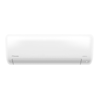
Model B
Use the holder at the back
of the unit against on the
mounting plate to prop up
the unit
Open the cover
and unscrew the
screws
Unscrew the
screws
If there is no refrigerant piping embedded in
the wall, do the following:
Step 3. Connect drain hose and refrigerant
piping (refer to Refrigerant Piping Connection
section of this manual for instructions).
Step 4. Keep pipe connection point exposed to
perform the leak test (refer to Electrical Checks
and Leak Checks section of this manual).
Step 5. After the leak test, wrap the connection
point with insulation tape.
Step 6. Remove the bracket or wedge that is
propping with insulation tape.
Step 7. Using even pressure, push down on the
bottom half of the unit. Keep pushing down
until the unit snaps onto the hooks along the
bottom of the mounting plate.
1. Based on the position of the wall hole relative
to the mounting plate, choose the side from
which the piping will exit the unit.
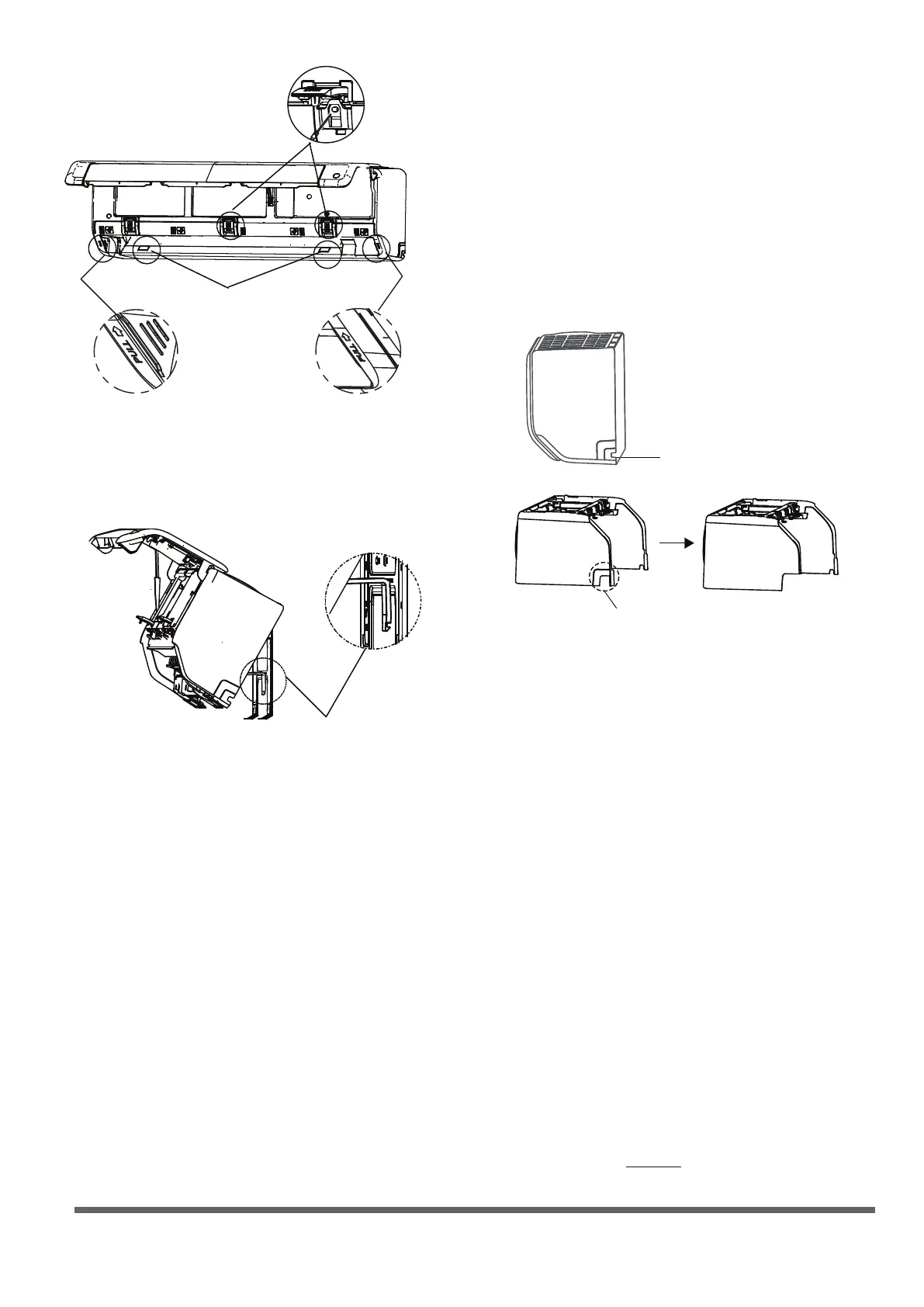
2. If the wall hole is behind the unit, keep the
knock-out panel in place. If the wall hole is to
the side of the indoor unit, remove the plastic
knock-out panel from that side of the unit.
(See gure below). This will create a slot through
which your piping can exit the unit. Use
needle nose pliers if the plastic panel is too
difcult to remove by hand.
3.
Use scissors to cut down the length of the
insulating sleeve to reveal about 40mm (1.57in)
of the refrigerant piping. This serves two purposes:
• To facilitate the Refrigerant Piping
Connection process.
• To facilitage Gas Leak Checks and enable
you to check for dents
Knock-out Panel
(cut depending on the
actual size needed)
If need to cut the big size plastic
panel, cut as shown above.
2. Use the holder at the back of the unit to
prop up the unit, giving you enough room
to connect the refrigerant piping, signal cable,
and drain hose.
4. Use the holder at the back of the unit to
prop up the unit, giving you enough room
to connect the refrigerant piping, signal cable,
and drain hose.
5.
Connect the indoor unit’s refrigerant piping
to the connective piping that will join the
indoor and outdoor units. Refer to the
Refrigerant Piping Connection section
of this manual for detailed instructions.
6. Based on the position of the wall hole
relative to the mounting plate, determine the
necessary angle of your piping.
7. Grip the refrigerant piping at the base of the bend.
8. Slowly, with even pressure, bend the piping
towards the hole. Do not dent or damage the
piping during the process.
Page 24
DO NOT kink the drain hose.
DO NOT
create a water trap.
DO NOT put the end of drain hose in
water or a container that will collect water.
BEFORE PERFORMING ANY
ELECTRICAL WORK, READ THESE
REGULATIONS
1. All wiring must comply with local and national
electrical codes, regulations and must be
installed by a licensed electrician.
2. All electrical connections must be made according
to the Electrical Connection Diagram located on
the panels of the indoor and outdoor units.
3. If there is a serious safety issue with the power
supply, stop work immediately. Explain your
reasoning to the client, and refuse to install the
unit until the safety issue is properly resolved.
4. Power voltage should be within 90-110% of
rated voltage. Insufcient power supply can
cause malfunction, electrical shock, or re.
5. If connecting power to xed wiring, a surge
protector and main power switch should be
installed.
6. If connecting power to xed wiring, a switch
or circuit breaker that disconnects all poles and
has a contact separation of at least 1/8in (3mm)
must be incorporated in the xed wiring. The
qualied technician must use an approved
circuit breaker or switch.
7. Only connect the unit to an individual branch
circuit outlet. Do not connect another appliance
to that outlet.
8. Make sure to properly ground the air conditioner.
9. Every wire must be rmly connected. Loose
wiring can cause the terminal to overheat,
resulting in product malfunction and possible re.
Do not let wires touch or rest against refrigerant
tubing, the compressor, or any moving parts
within the unit.
If the unit has an auxiliary electric heater, it must
be installed at least 1 meter (40in) away from
any combustible materials.
To avoid getting an electric shock, never touch
the electrical components soon after the power
supply has been turned off. After turning off
the power, always wait 10 minutes or more
before you touch the electrical components.
WARNING
BEFORE PERFORMING ANY ELECTRICAL
OR WIRING WORK, TURN OFF THE
MAIN POWER TO THE SYSTEM.
10.
11.
12.
Step 5:
Connect drain hose
By default, the drain hose is attached to the left-
hand side of unit (when you’re facing the back
of the unit). However, it can also be attached to
the right-hand side. To ensure proper drainage,
attach the drain hose on the same side that your
refrigerant piping exits the unit.
NOTE: In some locations of US, if the machine
has installed the conduit panel, please choose
right-hand side drainage.
Wrap the connection point rmly with Teon
tape to ensure a good seal and to prevent leaks.
Remove the air filter and pour a small amount
of water into the drain pan to make sure that
water flows from the unit smoothly.
NOTE ON DRAIN HOSE PLACEMENT
Make sure to arrange the drain hose
according to the following gures.
PLUG THE UNUSED DRAIN HOLE
To prevent unwanted leaks
you must plug the unused
drain hole with the rubber
plug provided.
CORRECT
Make sure there are no kinks
or dent in drain hose to ensure
proper drainage.
NOT CORRECT
Kinks in the drain hose
will create water traps.
NOT CORRECT
Do not place the end of the
drain hose in water or in
containers that collect water.
This will prevent proper
drainage.
NOT CORRECT
Kinks in the drain hose
will create water traps.
 Loading...